Sheet Metal vs CNC for Brackets and Enclosures
This comparison is for procurement and supply-chain managers sourcing brackets, panels, chassis or enclosures. It owns the commercial-comparison intent sheet metal vs CNC machining for brackets and enclosures and maps to one primary Money Page: sheet metal fabrication services.
Sheet metal or CNC: the direct decision rule
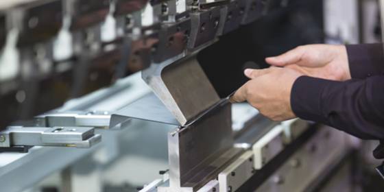
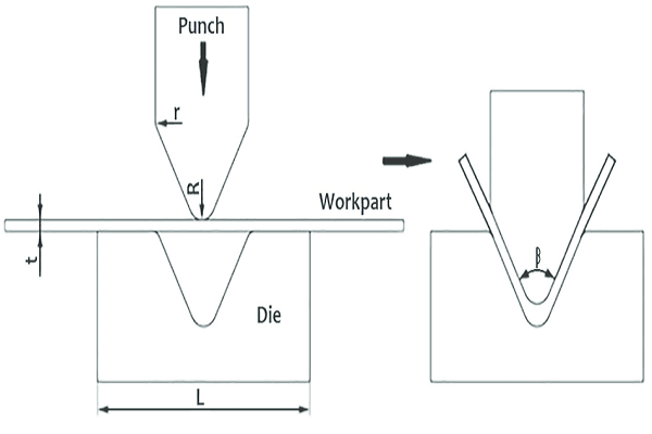
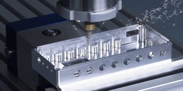
Start with whether the part behaves like folded sheet or like a solid machined body. Sheet metal is a strong route candidate when most walls share a specified sheet thickness and the geometry can be created with profiles, bends, tabs, hardware and joints. CNC machining is a strong candidate when the design relies on material remaining around deep pockets, integral mounting bosses, three-dimensional contours, precision bores, sealing lands or localized wall sections.
This is a screening rule, not a quote or capability promise. Material, part size, bend/tool access, workholding, quantity, finish and inspection can change the route. A hybrid assembly can also use a fabricated shell with selected machined inserts, plates or interfaces.
Sheet metal route signal
Consistent sheet thickness, developable walls, bends, vents, cutouts, inserts and joined construction.
CNC route signal
Solid geometry, pockets, integral bosses, controlled bores, sealing lands, contours or variable sections.
Decision table for brackets and enclosures
| Decision factor | Sheet metal review signal | CNC review signal | RFQ question |
|---|---|---|---|
| Basic geometry | Flat/developable panels connected by bends or joints. | Three-dimensional body removed from solid stock. | Can the released form be unfolded without changing function? |
| Wall strategy | Consistent specified sheet thickness is acceptable. | Variable wall sections or local mass are functional. | Which wall or rib relationships control stiffness and assembly? |
| Interfaces | Cut/formed openings and inserted or joined hardware can meet the requirement. | Integral threads, bores, datums or sealing faces drive the design. | Which interfaces are critical, and how are they measured? |
| Internal geometry | Tabs, partitions and separate formed components can create the layout. | Deep pockets, channels or integral bosses are required. | May the design use multiple joined components? |
| Appearance | Fold lines, seams and fasteners are compatible with the cosmetic plan. | A continuous machined body or localized machined finish is required. | Which faces are cosmetic, masked, sealed or grounded? |
| Quantity and change | Review cutting/forming setup and any dedicated tooling against expected revisions. | Review programming, setups, workholding and machining time against quantity. | Are prototype and repeat quantities quoting the same design? |
| Evidence | Formed and joined characteristics need an agreed inspection basis. | Machined features need drawing-led inspection tied to functional datums. | What report, sampling or material evidence is required per order? |
A comparison table cannot price the project. It identifies what must be made equivalent before suppliers compare routes or buyers compare quotations.
Geometry and interfaces usually decide before price
A box-like appearance can hide very different functional requirements. A simple folded cover, a gasketed enclosure with controlled sealing lands and a bracket with an integral bearing bore should not be evaluated with the same route assumptions. Mark the features that transmit load, locate mating parts, seal, ground, conduct heat or establish the inspection datum scheme.
ASME Y14.5 provides a standardized language for dimensional and geometric requirements in drawings and digital product definition. Its official overview supports a drawing-led comparison: control the features that protect form, fit and function rather than assuming the process name supplies a tolerance.
For thermal cutting, the ISO 9013 official record says its geometrical specifications apply when the drawing or pertinent documentation references them. A route comparison therefore needs the same specified cut and edge expectations, not a generic assumption about “laser accuracy.”
When a hybrid fabricated and machined route fits
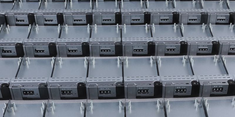
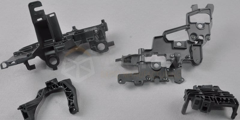
A hybrid route can keep a large cover, chassis or frame in fabricated sheet while adding machined plates, inserts, spacers or interface blocks only where the function requires them. This is not automatically better: the joints, datum transfer, finish sequence and inspection plan can add risk if they are not defined.
- Identify which interfaces truly need a machined surface or integral feature.
- Define how the machined component locates to the fabricated structure.
- Specify removable fasteners, permanent joints or welds and the assembly owner.
- Plan finish and masking around electrical, sealing, threaded and mating features.
- Agree whether components or the completed assembly control final acceptance.
The American Welding Society A2.4 record describes symbol-based communication of welding and examination information. When welding is part of the hybrid route, define the requirement rather than leaving the supplier to infer joint size or extent.
A buyer-controlled route-selection workflow
- Define the part’s job. Record loads, environment, mating parts, service access and the decision this build supports.
- Mark critical interfaces. Identify datums, bores, threads, sealing faces, grounding points, cosmetic zones and evidence needs.
- Screen sheet and solid geometry. Ask whether the function permits developable walls and joined construction or requires an integral body.
- Request route-specific feedback. Let the supplier identify forming, workholding, joint, stock or inspection risks without silently changing the design.
- Normalize the quotations. Compare the same revision, quantity, material, finish, hardware, inspection, packaging and shipping basis.
- Release the buyer decision. Approve the route, material, changes, deviations and acceptance criteria through controlled documentation.
A current Fictiv bridge-production guide identifies enclosures, brackets, chassis and panels as common sheet-metal candidates while noting that CNC-designed geometry may need modification. Neutral enclosure comparisons from Shengen and IMS Electronics likewise organize the decision around geometry and project scope. Their numerical thresholds and capabilities are not used as Sendot claims.
Watch the sheet metal route and compare a CNC bracket
RFQ package for a fair route comparison
- Current formed CAD, controlled drawing, part number, revision and units.
- Material, thickness or solid-stock requirement and approved substitution policy.
- Prototype and repeat quantities, with expected design-change status.
- Critical interfaces, mating parts, assembly and service-access needs.
- Bends, joints, welds, hardware and purchased-component responsibility.
- Finish, cosmetic zones, masking, sealing and grounding requirements.
- Inspection points, evidence requested per order and buyer acceptance criteria.
If the solid route remains necessary, review the supporting CNC machining service and the existing custom machined enclosure design guide. The primary conversion path for this article remains sheet metal fabrication.
Frequently asked questions
Is sheet metal always cheaper than CNC machining for an enclosure?
When should a bracket be CNC machined instead of bent?
Can sheet metal enclosures include threads and mounting hardware?
Can one enclosure use both sheet metal and CNC parts?
Who decides whether a supplier’s route change is acceptable?
Need a route review for a bracket or enclosure? Share the current files, quantities, critical interfaces, finish and evidence requirements.
Manufacturing next step
Apply this guidance to your part
Continue to the relevant service page for process scope and buyer inputs. If your design is ready, send the current files for engineering review and quotation.
Related manufacturing resources
Continue with the process or project stage most relevant to this topic: