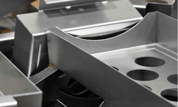
Sheet Metal Gauge Chart and Bend Allowance Guide (with Tables)
June 28, 2026
Sheet metal gauge is a number that represents thickness — the higher the gauge, the thinner the metal — and the actual thickness for a given gauge differs by material (steel, aluminum, and stainless each use a different standard). Use the charts below to convert gauge to millimeters and inches, then use the bend allowance formulas to lay out accurate flat patterns.
Key takeaways
- Higher gauge = thinner metal. The same gauge is a different thickness in steel vs aluminum vs stainless.
- Steel uses the Manufacturers’ Standard Gauge; aluminum uses the Brown & Sharpe gauge; stainless has its own.
- Bend allowance (BA) = the arc length of the neutral axis through a bend; add it to flat lengths to size the blank.
- The K-factor (≈0.3–0.45) locates the neutral axis and drives BA and bend deduction.
- Values below are nominal — always confirm against your supplier’s standard.
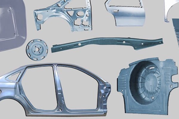
For the processes that use these numbers, see our sheet metal fabrication services and the sheet metal bending guide.
Sheet metal gauge chart (gauge to mm / inch)
Nominal thickness for common gauges. Note how the same gauge number is a different thickness in each material.
| Gauge | Steel (mm) | Steel (in) | Aluminum (mm) | Stainless (mm) |
|---|---|---|---|---|
| 7 | 4.55 | 0.179 | 3.67 | 4.76 |
| 10 | 3.42 | 0.135 | 2.59 | 3.57 |
| 12 | 2.66 | 0.105 | 2.05 | 2.78 |
| 14 | 1.90 | 0.075 | 1.63 | 1.98 |
| 16 | 1.52 | 0.060 | 1.29 | 1.59 |
| 18 | 1.21 | 0.048 | 1.02 | 1.27 |
| 20 | 0.91 | 0.036 | 0.81 | 0.95 |
| 22 | 0.76 | 0.030 | 0.64 | 0.79 |
| 24 | 0.61 | 0.024 | 0.51 | 0.64 |
Values are nominal reference thicknesses; tolerances and exact values vary by standard and supplier.
What is sheet metal gauge?
Gauge is a legacy numbering system for sheet thickness. It is counterintuitive: a higher gauge number means thinner material. Steel gauge follows the Manufacturers’ Standard Gauge, aluminum and other non-ferrous metals use the Brown & Sharpe (American Wire) gauge, and stainless steel uses its own gauge table — which is why the same gauge converts to a different thickness in each. When in doubt, specify thickness in mm or inches directly on your drawing.
Bend allowance, bend deduction, and the K-factor
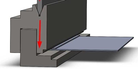
When sheet metal bends, the outside stretches and the inside compresses; somewhere between sits the neutral axis, whose length does not change. Laying out an accurate flat blank means accounting for this.
K-factor
The K-factor is the ratio of the neutral axis location to the material thickness (t). It typically ranges from about 0.3 to 0.45, with ~0.4–0.45 common for many bends. It depends on material, thickness, and bend radius.
Bend allowance (BA)
Bend allowance is the arc length of the neutral axis through the bend, which you add to the flat sections to get the total flat length:
BA = (π / 180) × A × (R + K × t)
where A = bend angle (degrees), R = inside bend radius, K = K-factor, and t = material thickness.
Bend deduction (BD)
Bend deduction is what you subtract from the sum of the two outside flange lengths to get the flat length:
BD = 2 × (R + t) × tan(A / 2) − BA
Design tips
- Keep one thickness per part where possible — it simplifies tooling and cost.
- Inside bend radius should usually be ≥ material thickness to avoid cracking.
- Hole and feature distance: keep holes and cutouts away from bends (≈2.5×t + R) so they do not deform.
- Confirm your fabricator’s K-factor and gauge standard before finalizing flat patterns. Read more sheet metal design tips.
Frequently asked questions
Is a higher gauge thicker or thinner?
Why is the same gauge a different thickness for steel and aluminum?
What is the K-factor in sheet metal?
How do I calculate bend allowance?
Need sheet metal parts made? Upload your CAD to Sendot Technology for a free DFM review and a quote on custom sheet metal fabrication. Request a quote.
Related manufacturing services
Explore how Sendot Technology can manufacture your custom parts: