High-Rigidity Robot Structural Components by CNC
TL;DR
Robot structural components are the load-bearing parts — arms, brackets, bases and frames — that hold a robot's geometry under acceleration. They are CNC machined rather than cast or fabricated because rigidity depends on tight tolerances and stable material: any deflection at the structure becomes positional error at the end effector, multiplied by the length of the arm.
- Rigidity, not strength, is the requirement — the part must not deflect, not merely survive. Stiffness is what holds accuracy.
- Error multiplies along the arm: a few hundredths of a millimetre at a joint face becomes visible error at the tool tip.
- Aluminum 6061/7075 for moving members (stiffness per unit weight — lower mass means lower inertia); steel and stainless for bases and wear points.
- Sendot machines to ±0.05 mm with surface finishes to Ra 0.2 µm, across 30+ materials, no MOQ.
- Same process covers automation hardware, packaging machine spare parts and general mechanical parts — send a drawing, get a quote in 12 hours.
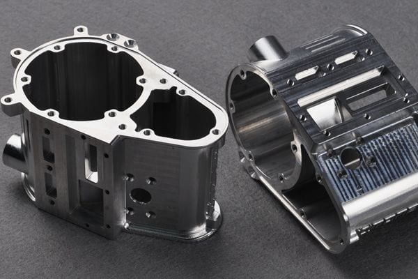
High-rigidity structural components for robotics and automation equipment, machined complete on our CNC centres. Robot arms, mounting brackets, bases and frames — plus automation hardware, packaging machine spare parts and general mechanical parts, made to your drawing. See our CNC machining services and send your CAD for a quote.
▶ Watch this video on Facebook
What makes a component "structural" in a robot?
A structural component is one that carries load and defines geometry — the arm sections, joint housings, mounting brackets, base plates and frames that everything else attaches to. It is distinct from the drive train (motors, gearboxes, belts) and from the end effector: those move the robot, the structure decides how accurately.
The demanding requirement is rigidity, and it is worth separating from strength. A strong part does not break. A rigid part does not bend. A robot arm that flexes 0.1 mm under acceleration has not failed by any strength measure — but the part it places is 0.1 mm out, every cycle, and the error grows with arm length. Stiffness is what buys repeatability.
Three properties follow from that:
- Dimensional accuracy at mating faces — every joint interface stacks into the final position, so tolerance at each face is cumulative.
- Low mass with high stiffness — a moving member's inertia is dead weight the drive must accelerate and stop. Lighter structure means faster cycles and smaller motors.
- Dimensional stability — the geometry must survive machining stress, temperature and time, not just leave the machine correct.
Why machined, not cast or fabricated
| CNC machined | Cast | Welded fabrication | |
|---|---|---|---|
| Tolerance | ±0.05 mm at Sendot | Loose as-cast; needs machining anyway | Distorts with weld heat |
| Rigidity | Highest — solid billet, no porosity | Good, but porosity is a risk | Depends on joint quality |
| Tooling | None | Pattern or die required | Fixtures and jigs |
| Low volume | Economic from 1 part | Needs volume to amortise tooling | Labour-intensive per unit |
| Design changes | A program edit | New tooling | Re-fixture and re-weld |
| Best for | Precision structure, prototypes to low volume | High-volume housings | Large frames, low precision |
Robotics rarely runs at die casting volumes, and the design usually keeps moving. That combination — precision, low volume, frequent revision — is exactly where machining wins. Where a program does reach volume, see our die casting services; for enclosures and guarding around the machine, sheet metal fabrication is usually the cheaper answer.
Materials for robot structural parts
| Material | Why | Typical use |
|---|---|---|
| Aluminum 6061 | Good stiffness-to-weight, machines cleanly, anodises well | Arm sections, brackets, plates |
| Aluminum 7075 | Substantially stronger than 6061; heavier duty | Highly loaded arms, joint housings |
| Steel | Maximum rigidity and wear resistance; heavy | Bases, gearbox mounts, wear surfaces |
| Stainless 304/316 | Corrosion resistance for washdown and food lines | Packaging and food-industry hardware |
| Engineering plastics | Light, self-lubricating, non-marking | Guides, guards, low-load covers |
The usual split: aluminum for anything that moves (inertia matters more than absolute strength), steel for anything that stays still and must not move at all. See aluminum CNC machining and 6061 vs 7075 for the alloy decision.
How a robot structural part is made
- 1Drawing & DFM review
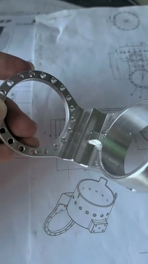
You send a 3D model (STEP, IGES, X_T) with a 2D drawing marking critical interfaces. We review manufacturability and flag anything that will cost more than it needs to — free with every quote. - 2Material selection
Alloy and stock condition chosen for stiffness, mass and stability. Pre-stress-relieved stock where the part is thin or highly machined. - 3Machining
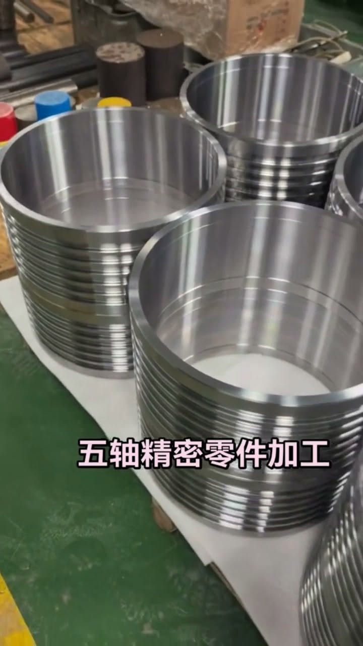
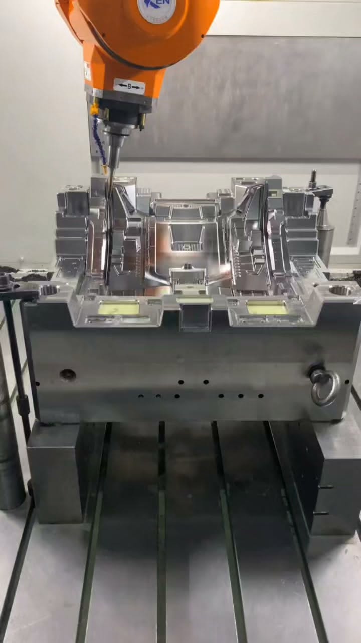
3-to-5-axis milling and turning. Five-axis matters here: complex geometry finished in one setup avoids the tolerance stack that repeated re-fixturing adds. - 4Stress relief & finishing
Where geometry demands it, stress relief between roughing and finishing so the part stays put. Then anodizing, bead blast, plating or powder coat. - 5Inspection
CMM verification of critical dimensions against the drawing, with a First Article Inspection report on request. - 6Delivery
Prototypes typically in 3–5 business days; production scheduled with your line.
Tolerances that matter — and where they matter
Not every dimension needs to be tight, and specifying that it does is the fastest way to make a part expensive. On a robot structural component the tolerance budget belongs at:
- Bearing and gearbox bores — where the drive train locates. Errors here become backlash and runout.
- Mating faces between arm sections — every joint stacks into final position, so this is where cumulative error is born.
- Mounting hole patterns — position tolerance, not just diameter; a correctly sized hole in the wrong place is still wrong.
- Datum surfaces — the references everything else is measured from. Get these wrong and the whole drawing means something different.
Everything else can run at general tolerances (ISO 2768 medium is normal), and should. Use GD&T to state what must be true — a position tolerance on a hole pattern communicates intent far better than four tightened coordinate dimensions. For fits, ISO 286 defines the shaft/hole system; for surface texture callouts, ASME B46.1.
See our CNC machining tolerances guide for the full chart.
Robot & automation parts at Sendot Technology
Sendot Technology machines robot structural components, automation hardware, packaging machine spare parts and general mechanical parts to drawing — prototype through low-volume production.
- Tolerance: to ±0.05 mm; surface finish to Ra 0.2 µm
- Processes: 3-to-5-axis CNC milling and turning, plus in-house finishing and assembly
- Materials: 30+ metals and engineering plastics — aluminum, steel, stainless, titanium, brass, POM, PEEK
- Volume: no MOQ — a single replacement part is a valid order
- Lead time: prototypes typically 3–5 business days
- Quality: ISO 9001 system, CMM inspection, FAI reports on request
- Quote: within 12 hours of receiving your CAD
Frequently asked questions
What are robot structural components?
Why do robot parts need to be CNC machined instead of cast?
Which material is best for a robot arm?
What tolerance do robotic and automation parts need?
Can you make one-off replacement parts for a packaging machine?
Related: precision CNC-machined robotics parts · CNC parts for automation equipment · 5-axis robotics rocker arm · product development prototyping.

Related manufacturing resources
Continue with the process or project stage most relevant to this topic: