
5-Axis CNC Machining for Automotive Mold Cavities
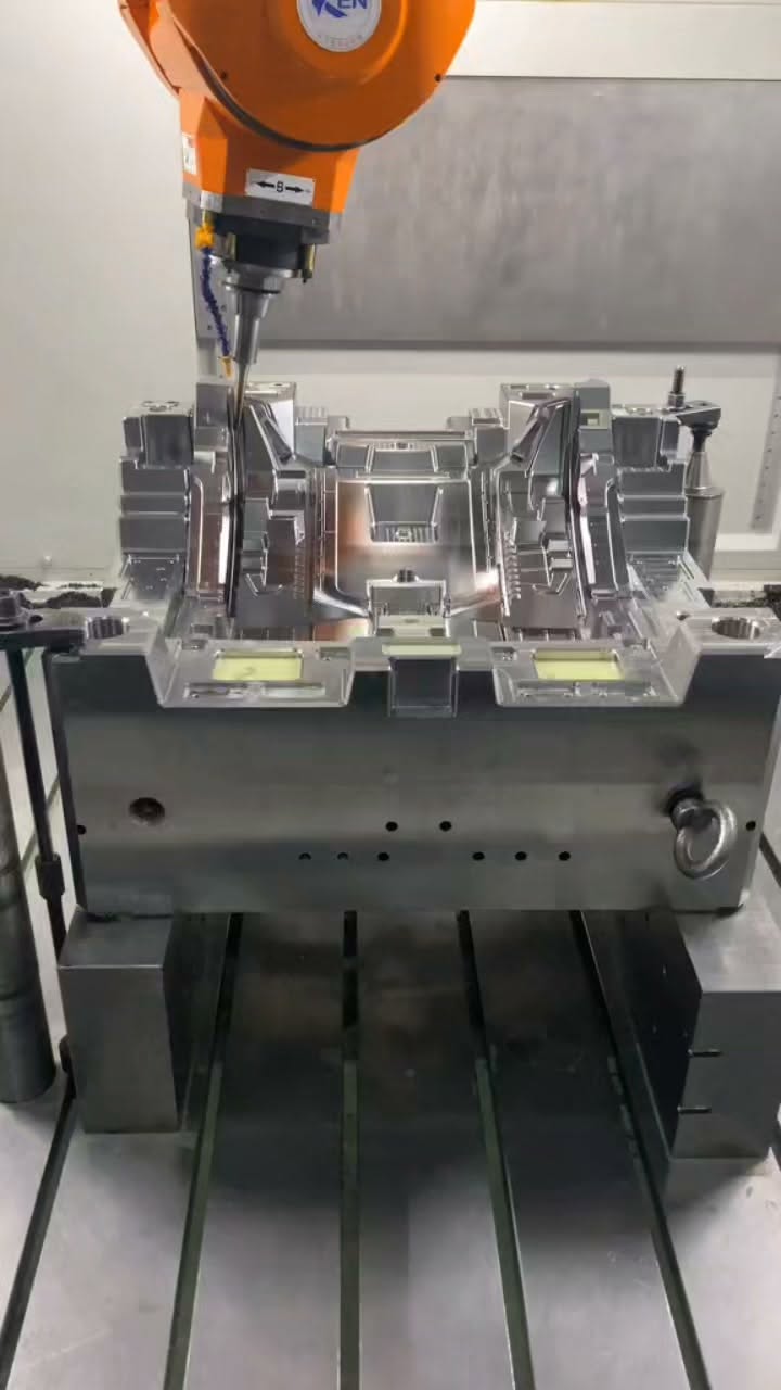
This video shows 5-axis CNC machining inside a contoured automotive mold cavity. It is most useful to tooling buyers comparing access to sloped faces, transitions and deep areas while keeping the cavity geometry tied to a controlled model. The quote package should define the tooling application, material and supplied condition, cavity and parting references, finish zones, electrode or secondary-process assumptions and inspection deliverables. Sendot's rapid tooling, CNC milling and automotive routes provide the closest commercial paths for a similar custom project.
Direct answer
What should buyers specify for automotive mold-cavity machining? Specify the controlled cavity and product geometry, tooling material and condition, parting and shutoff references, surface-finish or texture zones, secondary-process sequence, quantity and inspection deliverables. These inputs let the supplier select an access and finishing strategy that matches the actual tooling objective instead of a generic cavity process.
What the automotive cavity video shows
The cutter moves across complex internal surfaces while the workpiece is oriented for access. The footage demonstrates the machining stage of a custom cavity; the buyer's controlled model and tooling drawing still establish the surface definition, references and acceptance requirements.
Connect cavity surfaces to the tooling plan
Cavity depth, corner radii, steep walls, parting references and finish zones affect tool choice and sequence. Review the project through rapid tooling and CNC milling, with the intended vehicle-development use described on the automotive prototyping page.
Explore similar manufacturing options
For a comparable cavity or insert, use the closest tooling, milling and automotive application routes:
- Rapid Tooling Services — Closest option for mold and tooling projects
- CNC Milling Services — Closest process family for milled geometry
- Automotive Prototyping — Automotive application route
Technical specifications and sourcing inputs
| Attribute | Current video or sourcing definition | Source and scope |
|---|---|---|
| Application shown | Automotive mold cavity | Original Reel description Video-specific |
| Process shown | 5-axis CNC machining | Original Reel description and footage Video-specific |
| Geometry shown | Contoured internal cavity surfaces | Video footage Video-specific |
| Tooling material and condition | Define in the tooling drawing and RFQ | Buyer project package Project input |
| Finish and texture zones | Define on the controlled tooling drawing | Customer drawing Project input |
| Inspection deliverables | Define in RFQ or purchase order | Buyer quality requirement Project input |
5-axis cavity milling vs fixed-axis multi-setup milling
| Decision factor | 5-axis cavity route | Fixed-axis multi-setup route |
|---|---|---|
| Contoured access | Orient the cutter toward changing surfaces | Use accessible fixed directions |
| Deep or steep regions | Review rotary and tool clearance together | May require separate orientations or secondary methods |
| Reference strategy | Can retain a common setup | Relies on locating transfer between setups |
| Buyer decision | Best evaluated from full cavity geometry | Best evaluated from reachable feature groups |
Automotive cavity sourcing process
- Define tooling intent: Provide product, cavity and tooling data with the intended use.
- Review surfaces: Map access, references, parting, shutoffs and finish zones.
- Plan machining: Select stock, workholding, roughing, finishing and secondary operations.
- Machine and finish: Produce the approved cavity sequence and specified surface stages.
- Inspect and sample: Complete the agreed cavity evidence and any requested sample review.
Automotive mold-cavity sourcing checklist
- Provide the cavity and product models with controlled tooling drawings.
- Define insert or block material, supplied condition and process sequence.
- Map parting, shutoff, texture, polish and protected surface zones.
- Identify cavity references and the surface or dimensional evidence required.
- State the prototype, sample or low-volume objective and quantity.
Frequently asked questions
Why use 5-axis machining for a mold cavity?
What files support a mold-cavity quote?
How should cavity finish requirements be communicated?
Can Sendot support an automotive prototype tooling review?
Which inspection data should a tooling buyer request?
Related videos and guides
- Deep-Cavity Alloy Steel Housing Machining
- One-Setup 5-Axis CNC Aluminum Machining
- CNC Machining From 3D Model to Metal Part
- CNC Machining Service Guide
- Quality Assurance Process