Die Casting Defects: Porosity, Flash & How to Prevent
TL;DR
The most common die casting defects are porosity (gas and shrinkage voids), flash, cold shut, misrun, soldering and blisters — and nearly all of them trace back to three controllable levers: die design and venting, metal and die temperature, and injection pressure and speed. Fixing the die and the process window is almost always cheaper than sorting scrap downstream.
- Gas porosity is air or hydrogen trapped during a fill that takes only 20–100 milliseconds — controlled with venting, overflows, and vacuum assist.
- Shrinkage porosity forms in thick or isolated sections as metal solidifies; uniform walls (typically 1.5–4 mm in aluminum) are the primary defence.
- Flash is metal escaping the parting line — from insufficient clamp force, a worn or damaged die, or excessive injection pressure.
- Cold shut and misrun both mean the metal froze too early: raise metal or die temperature, or fill faster.
- Soldering is molten aluminum welding itself to the die — managed with die temperature, adequate draft (typically 1–3°), and die coatings.
- Internal porosity in aluminum and magnesium die castings is graded against ASTM E505 reference radiographs; NADCA product standards define what is acceptable.
Every die casting defect costs twice: once in scrapped metal, and again in the machining, finishing, and inspection already spent on a part that will not ship. This guide covers the defects you will actually meet in aluminum, zinc, and magnesium die casting — what each one looks like, what causes it, and the design or process change that prevents it.
See our die casting services, or start with what is die casting and our high-pressure die casting overview.
What causes die casting defects?
High-pressure die casting (HPDC) injects molten metal into a steel die in a few tens of milliseconds, at pressures that can exceed 100 MPa. Almost nothing about that is forgiving. But the failure modes are not random — they cluster around three levers:
- Die design and venting: where the gate is, how the metal flows, whether trapped air has anywhere to go (vents and overflows), and how the part is cooled.
- Thermal control: metal temperature, die temperature, and how evenly the die is held there across a production run.
- Shot profile: injection speed, injection pressure, intensification pressure, and clamp force.
When a defect appears, the useful question is which of those three moved. A cold shut is a thermal problem. Flash is usually a clamp or die-condition problem. Gas porosity is usually a venting and shot-profile problem. Diagnosing by symptom alone leads to guesswork.
Porosity: the defining die casting defect
Porosity is void space inside a casting. It is the defect most associated with die casting, and the reason die cast parts are traditionally not heat treated or welded. There are two distinct kinds, with two distinct causes — treating them as one problem is why porosity is so often "fixed" without improving.
Gas porosity
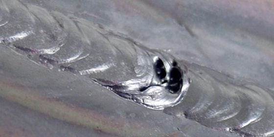
Gas porosity is trapped gas: air swept up by the metal front as the cavity fills, hydrogen dissolved in the melt, or steam and vapour from die lubricant burning off. Because the cavity fills in roughly 20–100 milliseconds, any air that has not been pushed out through a vent or overflow is simply trapped. The pores are typically rounded and smooth-walled — they were bubbles.
Controls: proper venting and overflows, gate and runner design that gives the metal front an ordered path, degassing the melt, controlled die lubricant, and — where the application demands it — vacuum-assisted die casting, which evacuates the cavity before the shot. Vacuum die casting is what makes structural die castings weldable and heat-treatable, because there is far less entrapped gas to expand. Sendot runs vacuum die casting for exactly these parts; specify it up front if yours will be welded, heat treated, or pressure tested.
Shrinkage porosity
Shrinkage porosity is a solidification defect. Metal contracts as it freezes; where a thick section or an isolated boss solidifies last and no molten metal can feed it, the void that opens has nowhere to go. The pores are typically jagged, angular and dendritic — they are the gaps between growing crystals, not bubbles.
Controls are mostly geometric, which is why this one belongs to the designer as much as the caster: uniform wall thickness, cored-out thick sections, generous radii, and gate placement that keeps a feed path to the last-to-freeze region open. Intensification pressure after the fill also helps push metal into forming shrinkage.
| Gas porosity | Shrinkage porosity | |
|---|---|---|
| Pore shape | Round, smooth-walled (bubbles) | Jagged, angular, dendritic |
| Where | Anywhere, often subsurface | Thick sections, bosses, last-to-freeze areas |
| Root cause | Entrapped air, hydrogen, lubricant vapour | Metal contracting during solidification |
| Design fix | Venting, overflows, gate/flow path | Uniform walls, core out thick sections, radii |
| Process fix | Vacuum assist, degassing, shot profile, lube control | Intensification pressure, die thermal balance |
| Tell-tale | Blisters after heat or paint bake | Leaks in pressure-tight parts; voids exposed by machining |
Flash
Flash is a thin fin of metal that escapes the die at the parting line, around ejector pins, or at slide interfaces. Some flash is normal and is trimmed. Flash becomes a defect when it is heavy, when it is persistent, or when it appears in places that are hard to trim cleanly.
Causes fall into three groups:
- Clamp force too low for the projected area — the shot simply pushes the die halves apart.
- Die condition — worn, eroded, or damaged parting surfaces; debris or previous flash preventing the die from closing fully.
- Shot profile — injection or intensification pressure higher than the die and machine can hold.
Heavy flash is worth chasing rather than trimming around: it raises trim cost, it can cause the die to wear faster, and it is often the first visible sign that the machine is undersized for the part or that the die needs maintenance.
Cold shut and misrun
These two are the same underlying failure — metal solidifying before the cavity is complete — at different severities.
- Cold shut (cold lap): two flow fronts meet but are too cool to fuse. It leaves a visible seam that is a genuine crack: the part is weak there even though it looks complete.
- Misrun (short fill): the metal freezes before the cavity is filled at all, leaving the part visibly incomplete — usually at the thinnest section or the point furthest from the gate.
Controls: raise melt and die temperature, increase injection speed so the cavity fills before the front chills, revisit gate location and size, and check that thin sections are not below what the alloy can actually run.
Soldering and drag marks
Soldering is molten metal chemically welding itself to the die surface — a particular problem with aluminum, which has a real affinity for steel. Once soldering starts, it tears the casting surface, accelerates die damage, and gets worse each shot. Controls: keep die temperature in the working window, maintain die coatings and lubricant, keep iron content in the alloy in specification, and ensure enough draft.
Drag marks (scoring) are scratches parallel to the ejection direction, caused by the part being dragged across the die as it is ejected. Root causes are insufficient draft (die casting typically wants 1–3°, more on interior walls), rough or damaged die surfaces, or ejection that starts before the part has shrunk free.
Blisters
Blisters are raised bumps that appear after casting — during heat treatment, paint bake, or powder coating. The mechanism is simple: subsurface gas porosity expands when the part is heated and lifts the skin. Blisters are not a new defect; they are pre-existing gas porosity announcing itself later, which is exactly why gas porosity limits what you can do to a die casting downstream. If parts must be heat treated or powder coated, that is a reason to specify vacuum assist up front.
Defect, cause and prevention at a glance
| Defect | Root cause | Primary prevention |
|---|---|---|
| Gas porosity | Entrapped air, hydrogen, lubricant vapour | Venting & overflows, degassing, vacuum assist, shot profile |
| Shrinkage porosity | Contraction during solidification with no feed path | Uniform walls, core out thick sections, intensification pressure |
| Flash | Low clamp force, worn die, excess pressure | Correct machine size, die maintenance, pressure control |
| Cold shut | Flow fronts too cool to fuse | Higher metal/die temperature, faster fill, gate revision |
| Misrun | Metal freezes before cavity fills | Higher temperature, faster fill, thicker minimum section |
| Soldering | Aluminum welding to the die steel | Die temperature control, coatings, draft, alloy iron content |
| Drag marks | Part dragged on ejection | More draft, die polish, ejection timing |
| Blisters | Subsurface gas expanding when heated | Reduce gas porosity at source (vacuum assist) |
How die casting defects are inspected
Surface defects — flash, misrun, drag marks, soldering — are caught visually and dimensionally. Internal porosity is the harder problem, because the part looks fine until it is sectioned, machined into, or pressure tested. Common methods:
- X-ray / radiography — the standard way to see internal voids without destroying the part. ASTM E505 provides reference radiographs specifically for grading discontinuities in aluminum and magnesium die castings.
- Sectioning — cut and polish a sample to measure porosity directly; destructive, used for process validation.
- Pressure / leak testing — the real acceptance test for housings, pump bodies, and valve parts, where interconnected porosity means a leak path.
- CMM and dimensional inspection — for the dimensional consequences of a defect (warp, short fill, flash-induced mismatch).
Acceptance criteria matter as much as the method. NADCA product specification standards and ASTM B85 (aluminum-alloy die castings) are the usual references — a drawing that says "no porosity" is not an achievable specification, whereas one that specifies a porosity grade in the critical region is.
Design rules that prevent defects
Most porosity arguments are won or lost in CAD, before anyone cuts a die:
- Keep walls uniform — typically 1.5–4 mm in aluminum. Uniform thin walls beat thick ones for both shrinkage and cycle time.
- Core out heavy sections rather than leaving a solid mass that will shrink internally.
- Add draft — typically 1–3°, more on interior surfaces, to prevent drag and soldering.
- Radius internal corners to keep metal flowing and reduce stress risers.
- Use ribs, not bulk, for stiffness — the same rule as injection molding design.
- Tell the caster which region is critical, so gates, overflows, and any vacuum assist can be arranged around it.
- Plan for post-machining — machining into a gas-porous region exposes the voids, so critical sealing faces need the porosity controlled there specifically.
For the wider trade-offs, see advantages and disadvantages of die casting and our comparison of die casting vs CNC machining vs investment casting.
Die casting at Sendot Technology
Sendot casts aluminum (ADC12, A380), zinc (Zamak 3/5) and magnesium, with tooling, post-cast CNC machining, finishing and assembly in house — so defect control, machining, and inspection stay with one supplier rather than being split across three.
- Vacuum die casting available — the direct answer to gas porosity when a part must be welded, heat treated, or pressure tight
- Machines 100–4,000 T; wall thickness 1.0–6.0 mm; as-cast tolerance ±0.1–±0.5 mm as-cast
- Tooling in 7–20 days, plus post-cast CNC machining of critical features to ±0.05 mm
- Finishing under one roof: powder coating, anodizing, plating, painting
- CMM inspection and an ISO 9001 quality system
- Free DFM review with every quote — send the CAD and tell us the critical region
Frequently asked questions
What is the most common die casting defect?
Can die casting porosity be eliminated completely?
Why do blisters appear on die cast parts after powder coating?
How is porosity in a die casting measured?
What wall thickness and draft should I design for die casting?
How do I get a die casting quote with a defect review?

Manufacturing next step
Apply this guidance to your part
Continue to the relevant service page for process scope and buyer inputs. If your design is ready, send the current files for engineering review and quotation.
Related manufacturing resources
Continue with the process or project stage most relevant to this topic: