Engineering Drawing for CNC Machining: Release Checklist
This guide is for mechanical and product engineers preparing a drawing-led package for an engineering-verification build. It focuses on clear decision inputs rather than fixed capability promises.

What belongs on a CNC-ready engineering drawing?
A drawing is most useful when it lets design, manufacturing and inspection discuss the same revision. The ASME Y14.5 overview describes dimensioning and tolerancing as a common language; the applicable standard and revision should be identified by the buyer where required.
| Drawing area | Decision it controls | Before release, confirm |
|---|---|---|
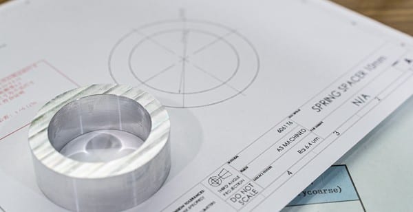
| Title block and revision | Which document governs | Part ID, units, revision and release owner match the CAD package. |
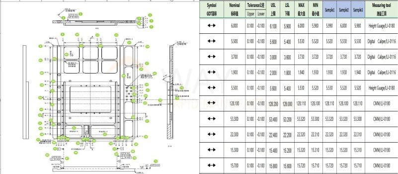
| Views and sections | How geometry is read | Internal, angled and hard-to-see features are unambiguous. |
| Dimensions and GD&T | Functional relationships | Critical features reference functional datums rather than chained dimensions. |
| Material and finish notes | Project requirements | Grade, condition, finish and protected surfaces are stated where applicable. |
| Inspection notes | Acceptance planning | Characteristics and requested evidence are agreed per drawing and order. |
3D CAD and 2D drawing: complementary, not competing
Communicates solid geometry, feature relationships and design context.
Identifies revision, dimensions, datums, notes, finishes and acceptance requirements.
Uses both files with quantity and requirement inputs to discuss manufacturability.
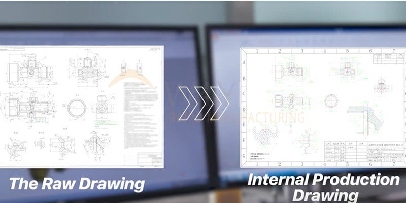
Release workflow for a machined-part drawing
- Start from function: identify mating surfaces, interfaces and features that affect assembly or verification.
- Select clear views: add section or detail views where a feature cannot be read reliably in the main projection.
- Define relationships: dimension from functional references and use datum references where geometric control is needed.
- Control the package: align drawing, CAD, material, finish and revision identifier before sharing.
- Review and release: resolve questions, then have the buyer issue the approved design and acceptance criteria.
Use datum references to protect assembly intent
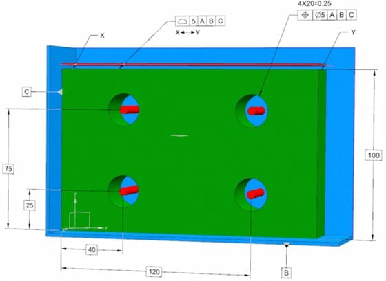
Datums are not merely convenient edges for dimensioning. They establish a reference framework for the relationships that matter to the part’s function. The ISO GPS handbook describes GPS as an international symbol language for communicating product requirements across organisations. Read the companion guide on datums in CNC machining drawings before assigning a datum scheme.
What to send for engineering review
For a controlled manufacturing discussion, pair the released drawing and model with material, quantity, finish, change status and the inspection requirements relevant to the project. The Design and Engineering Verification route explains how those inputs support a drawing-led review. A supplier may provide DFM feedback; that feedback does not replace the buyer’s final design approval, deviation approval or acceptance decision.
See the real CNC machining process from 3D model to metal part video for the file-to-part context, then use the CNC quote file formats guide to prepare the transfer package.
Frequently asked questions
Is a 3D model enough for a CNC machining drawing package?
Who approves a drawing after DFM feedback?
What should the title block control?
When should I add a section view?
Can inspection requirements be assumed from a drawing?
References
Manufacturing next step
Apply this guidance to your part
Continue to the relevant service page for process scope and buyer inputs. If your design is ready, send the current files for engineering review and quotation.
Related manufacturing resources
Continue with the process or project stage most relevant to this topic: