Datums in CNC Machining Drawings: A Functional Guide
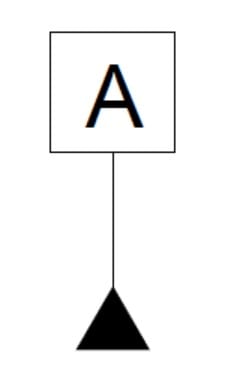
This guide is for engineers defining assembly-critical features before an engineering-verification build or a drawing-led RFQ.
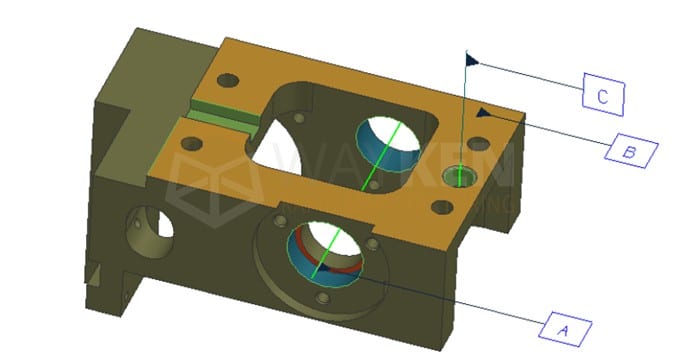
What is the difference between a datum and a datum feature?
A datum is the theoretically exact reference used by a specification; a datum feature is the real part feature identified to establish that reference. This distinction matters because a real surface, hole or axis has variation, while the design reference expresses the intended relationship. The ASME Y14.5 overview includes datum references and degrees of freedom among the standard’s subjects.
| Term | Role on the drawing | Project question |
|---|---|---|
| Datum feature | Actual surface, feature of size or target identified on the part. | Can this feature represent how the part functions? |
| Datum | The exact reference derived for specification and evaluation. | Which relationship is this reference intended to protect? |
| Datum reference frame | Ordered primary, secondary and tertiary references. | Does the order match seating, locating and clocking in assembly? |
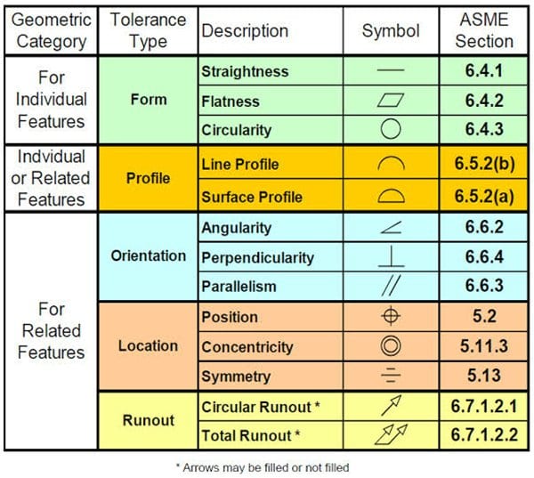
| Feature control frame | Connects geometric control to the required reference frame. | Are basic dimensions and datum references coherent? |
Choose datums from assembly function
Begin with the interface that stabilises the part in its end use. A mounting face may be a stronger primary reference than a visually large but non-functional surface; a locating bore or pilot may matter more than a nearby edge. The correct scheme is part-specific, so avoid copying a datum order from another component.
Starts from the surface, axis or feature that seats and locates the component in use.
May be easy to dimension or access, but can miss the relationship that affects fit.
Confirm the selected features are stable, accessible and aligned with the buyer’s approved intent.
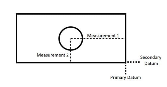
Datum-selection workflow
- Map the assembly: identify seating surfaces, locating features, orientation and interfaces that affect function.
- Pick the primary reference: choose the feature that best represents stable seating or the principal functional plane.
- Add secondary and tertiary references: use them to locate and orient the part without creating an unintended chain of dimensions.
- Connect controls: apply basic dimensions and GD&T only where the functional relationship requires them.
- Review the controlled revision: check the model, drawing, inspection needs and any DFM questions before buyer release.
How datums connect design, machining and inspection
One drawing may inform several project decisions, but those decisions are not interchangeable. The design datum scheme states the intended part relationship. A manufacturing team may plan workholding and setup references to produce that relationship. Inspection planning evaluates characteristics against the drawing and the agreed order. Keep those roles explicit instead of treating a convenient setup point as an automatic substitute for approved design intent.
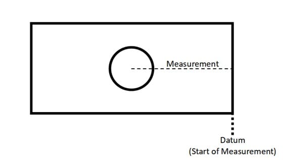
Prepare a datum discussion for engineering review
Share the controlled CAD and drawing revision, assembly context where relevant, material and finish requirements, critical interfaces and the inspection evidence requested for the order. The Design and Engineering Verification page explains the drawing-led review path. For related content, see engineering drawings for CNC machining and the GD&T guide.
Watch the directly related CMM inspection for geometric tolerance video for visual inspection context. Availability of any inspection method or documentation remains subject to the project drawing and agreed order.
Frequently asked questions
How many datums should a CNC drawing use?
Should the largest surface always be datum A?
Can a machining setup reference replace the drawing datum?
When should datum features be reviewed?
Do datums guarantee an inspection report?
References
Manufacturing next step
Apply this guidance to your part
Continue to the relevant service page for process scope and buyer inputs. If your design is ready, send the current files for engineering review and quotation.
Related manufacturing resources
Continue with the process or project stage most relevant to this topic: