
CNC Machining Process: From 3D Model to Metal Part
This video follows a CNC project from the digital model to machining and a finished metal component. The model communicates geometry, but a buyer-ready package also needs a controlled drawing for tolerances, datums, threads, finishes and acceptance criteria. A supplier then reviews manufacturability, selects stock and workholding, prepares toolpaths, machines the part and completes the agreed inspection. The page is for buyers who want to understand what information moves a custom CNC part from an initial file to a quotable, controlled order.
Direct answer
How does a 3D model become a CNC machined metal part? The supplier reviews the model and controlled drawing, confirms material and requirements, plans datums and workholding, creates CAM operations, machines and deburrs the component, applies the specified finish, and inspects the agreed characteristics. Revision control connects every stage to the same approved design and acceptance criteria.
What the CAD-to-part video shows
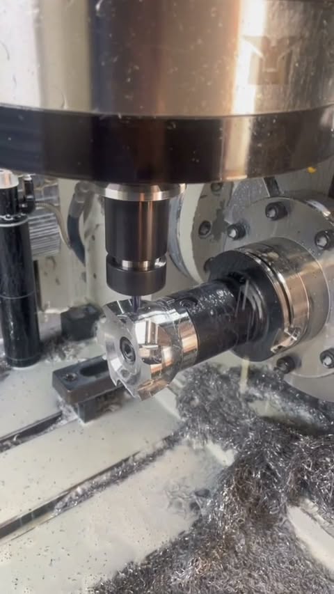
The Reel shows a digital model, active machining and the finished component. It illustrates the physical conversion of geometry into a metal part. Commercially, the important transition happens when the model is paired with revision, material, quantity, finish and acceptance requirements.
Why the model and drawing serve different jobs
The 3D file supports geometry review and CAM preparation. The controlled drawing identifies requirements that may not be safely inferred from geometry alone. Begin with design and engineering verification, continue to CNC machining, and define the evidence package through quality assurance.
Explore similar manufacturing options
Use these Sendot routes to move a custom model from design review into machining and inspection:
- Design and Engineering Verification — DFM and design verification route
- CNC Machining Services — Primary manufacturing service
- Quality Assurance — Inspection planning and documentation
Technical specifications and sourcing inputs
| Attribute | Current video or sourcing definition | Source and scope |
|---|---|---|
| Starting data | 3D model | Original Reel description and footage Video-specific |
| Process shown | CNC machining | Original Reel description and footage Video-specific |
| Output shown | Finished metal component | Original Reel description and footage Video-specific |
| Material grade | Define in RFQ and drawing | Buyer project package Project input |
| Tolerances, datums and threads | Define on the controlled drawing | Customer drawing Project input |
| Finish and inspection package | Define in RFQ or purchase order | Buyer project package Project input |
3D model only vs model plus controlled drawing
| Sourcing need | 3D model only | Model plus controlled drawing |
|---|---|---|
| Geometry review | Supports shape and feature review | Supports shape plus controlled requirements |
| Tolerance intent | May leave priorities unclear | Identifies dimensions, datums and geometric controls |
| Finishes and notes | Usually limited | Can define finishes, threads and protected areas |
| Inspection planning | Provides geometry context | Maps acceptance characteristics to revision |
CAD-to-part manufacturing flow
- Review: Check the model, drawing, revision, material and quantity.
- Plan: Resolve DFM issues and define stock, datums, workholding and inspection.
- Program: Create and review roughing, drilling and finishing operations.
- Produce: Machine, deburr, clean and apply the specified finish sequence.
- Verify: Inspect the agreed characteristics and release the requested records.
What to include in a CAD-to-part RFQ
- Native or neutral 3D model and revision-controlled drawing.
- Material grade and supplied condition.
- Quantity, target schedule and any staged prototype or repeat-order need.
- Finish, protected surfaces and post-process sequence.
- Critical characteristics, sampling and report format.
Resolve any model-to-drawing conflict before programming and release the approved revision to production.
Frequently asked questions
Is a 3D model enough for a CNC quote?
Which CAD formats can I send?
When does DFM happen in the CNC process?
How are drawing changes handled after quoting?
What should accompany the CAD files?
Related videos and guides
- One-Setup 5-Axis CNC Aluminum Machining
- Deep-Cavity Alloy Steel Housing Machining
- CMM Inspection of an Aluminum Motor Housing
- CNC Machining Service Guide
- GD&T Guide