
Design for Manufacturing (DFM) for CNC Machining
Design for Manufacturing (DFM) is the practice of designing parts so they are easy, fast and cheap to manufacture without sacrificing function. For CNC machining, most of a part’s cost is locked in at design time — so applying a handful of DFM rules around geometry, tolerances, GD&T and surface finish is the highest-leverage way to reduce cost and lead time. This hub is your starting point, linking to detailed guides for each topic.
Key takeaways
- DFM decisions made at design time drive most of a machined part’s cost — get them right first.
- The four levers: machinable geometry, sensible tolerances, correct GD&T, and the right surface finish.
- Round internal corners, keep walls thick enough, avoid deep/thin features, and loosen non-critical tolerances.
- Standard tolerance is ISO 2768-m (±0.1 mm) and standard finish is Ra 3.2 µm — only tighten where function requires.
- Sendot provides a free DFM review with every quote.
What is Design for Manufacturing?
DFM aligns a design with the realities of the manufacturing process. For CNC machining, that means designing around how cutting tools work — their size, reach and rigidity — and communicating requirements (tolerances, geometry, finish) clearly so nothing is over- or under-specified. Good DFM lowers cost, improves quality and shortens lead time all at once.
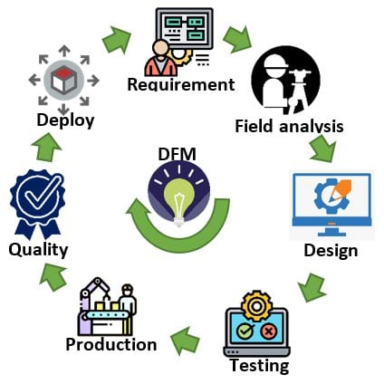
The DFM toolkit: four in-depth guides
This cluster covers everything you need to design a manufacturable machined part:
| Topic | What it covers | Guide |
|---|---|---|
| DFM design rules | Wall thickness, radii, holes, pockets, threads, undercuts | 12 DFM rules for CNC machining |
| Tolerances | Standard tolerance, ISO 2768 chart, achievable precision, cost impact | CNC machining tolerances |
| GD&T | The 14 symbols, datums, feature control frame, MMC/LMC | GD&T basics |
| Surface finish | Ra chart, roughness by process, how to specify finish | Surface roughness (Ra) chart |
1. Design machinable geometry
Round internal corners (end mills can’t cut sharp ones), keep walls at least 0.8 mm in metal, avoid pockets deeper than ~4× the tool diameter, and make features reachable from standard tool directions. Full checklist with target values: 12 DFM rules for CNC machining.
2. Specify sensible tolerances
Put a general tolerance on the drawing (ISO 2768-m is the usual default) and tighten only the few dimensions critical to fit or function — blanket-tight tolerances are the biggest avoidable cost driver. Chart and achievable values: CNC machining tolerances.
3. Use GD&T where it matters
Geometric tolerancing communicates function — form, orientation, location and runout relative to datums — more precisely than plus/minus dimensions, and often allows a wider manufacturable tolerance. Learn the symbols: GD&T basics.
4. Choose the right surface finish
The default as-machined finish (Ra 3.2 µm) is fine for most parts; specify finer finishes only where sealing, sliding, fatigue or appearance requires it, since each step finer adds an operation. See the Ra chart and our parts finishing options.
Material choice is part of DFM
The most machinable material that meets your requirements is usually the cheapest to make — aluminum machines far faster than steel or titanium. Compare options in the materials hub, then get a price on precision machining.

DFM review for CNC machining: turn a drawing into a manufacturable part
A CNC DFM review is a design review for machined parts before the purchase order is released. It checks whether tool access, wall thickness, internal radii, hole depth, datums, tolerances and finish callouts match the part’s function and a practical inspection method. The aim is not to make every feature looser; it is to identify the few requirements that create cost, lead-time or yield risk without contributing to function.
What to send for a useful CNC design review
- Geometry: STEP or equivalent 3D model plus the released 2D drawing.
- Function: mating, sealing, load, thermal or appearance requirements that explain why a feature is critical.
- Production context: prototype, pilot or repeat quantity; material and finish; target timing.
- Quality context: critical dimensions, GD&T datums and requested inspection evidence.
- Decision rule: a supplier can flag trade-offs; the design authority decides whether a change is acceptable.
If the review confirms a CNC route, see custom CNC machining services. If a feature or quantity makes another process more economical, compare low-volume manufacturing options before tooling is committed. For the common drawing details that raise cost without helping function, read drawing callouts that raise machining cost.
CNC DFM review FAQ
What does a DFM review for CNC machining check?
Does DFM review mean the supplier changes my design?
When should I request a CNC DFM review?
Frequently asked questions
What is Design for Manufacturing (DFM)?
Why is DFM important for CNC machining?
What are the most important DFM rules?
What is the standard tolerance and finish for machined parts?
Sources & further reading: ISO 2768 general tolerances · ASME Y14.5 dimensioning & tolerancing · ISO 1302 surface texture indication.
Design for manufacturing, past the definition
Most explanations of design for manufacturing stop at “design parts so they are easy to make” — true, and useless in front of a real drawing. In practice, design for manufacture is a negotiation: every line in your model asks a machine to do something, and some requests cost far more to grant than others. A DFM review finds the requests you did not mean to make. A 0.5 mm internal corner radius in a deep pocket is rarely functional — it is a sketch default — yet it forces a slender cutter, a slow feed and a long cycle when the pocket would work identically at R6.
What DFM is not
- Not cost-cutting. A change that degrades function has failed, whatever it saved.
- Not the supplier deciding your design. A review flags and explains — only you know what the part must survive.
- Not the same across processes. Thicker walls make a machined part cheaper and a die cast part worse.
Design for manufacturing principles
Rule lists are downstream of principles. The machining numbers live in our 12 DFM rules for CNC machining and the background in our overview of DFM principles, objectives and uses. Here is the reasoning behind them, which is what handles the cases no rule list covers.
Design to the natural motion of the process
Every process wants one motion: a cutter sweeping an arc, a brake folding a straight line, metal filling a cavity and shrinking. Geometry that follows the motion is nearly free; geometry that fights it is paid for in tooling, setups or scrap.
Every constraint is charged again on every part
A blanket ±0.05 mm does not make a part more reliable — it makes every dimension an inspection point. Set a general tolerance, tighten only what fit or function needs. Consistently the largest avoidable cost we see.
Setups multiply everything
Each re-clamping costs handling, a new datum reference, and positional error between setups. So “can these two features be reached from the same direction?” improves accuracy and cost at the same time — rare in engineering.
Put the variation where it is cheap
An assembly absorbs a fixed amount of variation. Decide where it lives: on the bore that is expensive to hold, or on a clearance slot that costs nothing to open. Allocating a stack-up beats tightening everything.
Standard beats optimal, and design for inspection
Standard drills, threads and stock sizes cut with tooling already on the shelf; a dimension chosen because it is 4% lighter can add days waiting for a tool. And a feature nobody can measure cannot be guaranteed — check a probe reaches it, and state the datums. See the manufacturing glossary for datum and true position; the ISO committee for geometrical product specification keeps that language portable between your engineers and ours.
A design for manufacture example: an aluminium sensor housing
A composite of reviews we run weekly. The part: a 6061-T6 sensor housing, roughly 92 × 62 × 34 mm, with a sealed cavity, an optical sensor bore, a cable gland and four mounting features; 25 samples, then batches of 250. Nothing in the model was wrong. It held six requests the designer had not consciously made.
| # | Original | Change | Reason | Effect |
|---|---|---|---|---|
| 1 | Cavity 18 mm deep, R1.5 mm internal corners | Corners to R6 mm | R1.5 forces a 3 mm cutter reaching 18 mm: 6:1 stick-out, deflection, chatter. R6 lets a 10 mm cutter work at 1.8:1. | Heavy roughing passes instead of many light ones, and no special slender tool to source, so the part stays inside the 3–5 working day sample window. |
| 2 | One outer wall at 0.9 mm | Thicken to 2.0 mm | 0.9 mm clears our 0.8 mm floor, but a floor is not a target: that wall vibrates as the cutter passes. | Removes a hand-finishing operation and the scrap risk, for about 12 g of aluminium. |
| 3 | Gland pilot Ø3 mm × 27 mm deep (9:1) | Ø4 mm × 16 mm deep (4:1) with counterbore | Past roughly 4× diameter, drilling needs peck cycles and broken-drill risk dominates. The gland needed clearance, not depth. | Standard drill, standard cycle, no rescue operation on a nearly finished part. |
| 4 | Features on five faces, two M4 tapped holes underneath | Those holes moved to a side face already machined | They fixed a bracket that could equally be bolted from the side, so they were buying a whole extra setup. | Four setups become two, and the mounting features now share a datum with the sensor bore instead of inheriting setup-to-setup error. |
| 5 | ±0.05 mm on all 34 dimensions | ISO 2768-m general; ±0.05 mm on bore, O-ring groove, bore-to-face location | Three dimensions were critical. The other 31 were tight by inheritance from a template title block. | Inspection drops from every dimension to three controlled characteristics — the biggest saving here, and it grows with batch size. |
| 6 | Ra 0.8 µm on every external surface | As-machined Ra 3.2 µm outside, then blast and anodise; Ra 0.8 µm kept on the sealing face | The fine finish was for appearance, but blast and anodise define the look, not the tool marks under them. | Removes a semi-finishing pass over the whole exterior. We hold Ra 0.2 µm where it earns its place; here that was one face. |
No headline percentage, deliberately: change 5 scales with quantity, change 4 with handling, change 1 shows up as lead time. What is precise is what disappeared — two setups, one special tool, one finishing pass, one deburring operation, and thirty-one inspection points, each of which was a measurement someone had to take and record (NIST publishes useful public material on that measurement practice).
The two changes we told them to reject
- Opening the bore-to-face location to ±0.1 mm. It looked like a classic over-tolerance. It was not: the sensor is optically aligned to that face and the budget was already allocated. When a tight tolerance is load-bearing, holding it is the cheap option and a field failure is the expensive one.
- Splitting the deep cavity into a two-piece bolted housing. Genuinely easier to machine — and it adds a second sealing joint to a part whose job is keeping water out. Trading a manufacturing problem for a reliability problem is not DFM.
The rule: reject any suggestion where the expensive feature is the reason the part works; take the ones where nobody can say what the expensive feature is for.
The design for manufacturing process, step by step
How a review runs on our side, from files arriving to a drawing we will cut to.
- File intake. Check the model is watertight, correctly scaled and in the units the drawing implies. STEP preferred; also IGES, X_T, DWG, PDF, STL, and DXF for 2D laser-cut sheet.
- Intent before geometry. What it mates with, seals against and carries, plus quantity and date. Without this a reviewer can only apply generic rules, which is how bad suggestions get made.
- Process selection. Machined, folded, cast or moulded — and does that still hold at your quantity? A bracket at 50 pieces and at 50,000 are different design problems.
- Geometry review. Wall thickness, radii against pocket depth, hole depth-to-diameter, tool access, thin or tall features, undercuts.
- Setup and fixturing plan. How many re-clamps, what the part sits on first, which features must share a setup. Several geometry findings usually resolve here at once.
- Tolerance, GD&T and finish review. Separate critical characteristics from inherited ones, check datums are real and reachable, confirm each finish callout does a job. Practice follows the dimensioning and tolerancing standards published by ASME and ISO.
- Material and post-processing check. Coatings add thickness and heat treatment moves geometry, so both must be checked against the tolerances — and the grade must exist in the stock size the part needs.
- Findings returned with the quote. Each one marked blocker, cost driver or observation, with the reason — within 12 hours of usable CAD, as part of the quote rather than an extra service.
- Decision and drawing release. You accept, modify or reject each item; nothing changes without written approval. The approved revision is what we make and inspect to under our ISO 9001 system.
- First article, then feedback. Measured parts reveal what paper review cannot, and those findings go into the drawing before the production batch, not after.
Steps 1–8 are what buyers usually mean by the DFM process. Steps 9 and 10 get skipped, and that is where the expensive surprises live.
Design for manufacture and assembly: how DFM and DFA differ
Design for manufacture and assembly pairs two disciplines that are taught together and applied separately. DFM optimises making each part; DFA optimises what happens once parts exist — handling, orienting, joining, testing. The combination, popularised as DFMA by Boothroyd and Dewhurst, matters because the two pull in opposite directions.
| DFM | DFA | |
|---|---|---|
| Optimises | Cost, time and yield of producing one part | Cost, time and error rate of joining parts |
| Typical moves | Open a radius, thicken a wall, loosen a non-critical tolerance, remove a setup | Cut part count, delete fasteners, add self-locating features, allow one-direction assembly |
| Measured by | Cycle time, setups, tooling, scrap, inspection load | Part and fastener count, handling time, chances to mis-assemble |
| Fails when | A feature is simplified that the function needed | Integration creates one part too complex or risky to make |
Where they collide: DFA says merge three brackets into one machined block, deleting six fasteners and two alignment steps. DFM answers that the block needs deep pockets, five-face access and 70% of its stock removed — and that scrapping it costs three parts’ work instead of one. Both are right; the answer depends on assembly labour, volume and tolerance for field failure. The reverse collision is as common: DFA loves snap features and locating lugs, which are undercuts in a machined part and nearly free in a moulded one.
Sequence: DFA first, at concept, because part count is architectural and merging parts later means restarting. Then choose the process per surviving part, run DFM on each, and re-check the assembly — DFM moves tolerances, and a loosened bore that was fine alone can break a stack-up. Finally prototype the assembly, not only the parts: handling problems are invisible in CAD, and with no MOQ on machined and sheet metal parts, one real set before committing tooling is cheap insurance.
Process-specific DFM: the same decision, opposite answers
The common expensive mistake is carrying machining habits into a casting, or casting habits into sheet metal. The principles hold; the rules invert.
| Decision | CNC machining | Sheet metal | Die casting | Injection moulding |
|---|---|---|---|---|
| Wall thickness | Thicker is cheaper — stiffness resists cutting force. 0.8 mm is a limit, not a target. | Set by stock gauge, not by you: we work 0.5–6 mm, so pick a standard gauge. | Uniformity beats value. We cast 1.0–6.0 mm; thick sections trap gas and shrink, giving porosity. | Thin and uniform. Thick sections sink, and cooling dominates cycle time. |
| Internal corners | Must be radiused; bigger radius, bigger and faster cutter. Aim for a third of pocket depth. | Inside bend radius at least material thickness, or harder alloys crack. | Radius everywhere for flow and die life; sharp corners are stress risers in the die. | Radius everywhere for flow and to avoid stress concentration. |
| Ribs and bosses | Expensive — the machine removes everything around them. Prefer a thicker wall. | Made as bends, flanges and gussets, not added material. | Cheap and preferred: stiffness without thickening a wall. | Cheap, but keep rib thickness well under the wall or it shows as a sink mark. |
| Draft and undercuts | No draft; undercuts cost a special tool or an extra setup. | No draft; undercuts usually need a secondary operation. | Draft required on faces perpendicular to the parting line; undercuts need side actions. | Draft required, more on textured faces; undercuts need side actions or lifters. |
| Realistic tolerance | ±0.05 mm on critical features; Ra 0.2 µm where specified. | ±0.1 mm on cutting; formed dimensions accumulate more and should be looser. | ±0.1 to ±0.5 mm as cast; machine only what needs better. | Governed by shrinkage, which varies with resin and section; confirmed at quotation. |
| Late change, quantity | Cheap: reprogram and re-cut. No MOQ. | Cheap: new flat pattern. No MOQ; simple parts 3–7 working days. | A steel change to the die. Tooling 7–20 days, MOQ 1,000–3,000 pcs, ADC12 / A380 and Zamak 3 / 5, 100–4,000 T, parts to 50 kg. | Tooling-led; confirmed at quotation. |
So if a part may migrate from machined prototypes to die cast production, design it for the casting on day one and machine the prototypes to that geometry; adding draft and uniform walls later means re-validating everything. Route detail: CNC machining, sheet metal fabrication, die casting.
Design for manufacturing services: what our free review covers
Buyers searching for design for manufacturing services meet two kinds of offer. One is automated: upload a model, get instant geometry feedback. Protolabs, Xometry, Hubs and Fictiv all do this well, and for a fast go/no-go it is the quickest option available. The other is a person reading your drawing — slower, back within 12 hours rather than 12 seconds, but a human can ask why a tolerance exists where an algorithm can only measure that it does.
Included with every quote, at no cost
- Geometry flags: thin walls, tight radii, deep or slender features, unreachable areas, undercuts.
- Tolerance and finish review: which callouts drive cost, and whether the datum scheme is measurable.
- Setup implications: what changes if two features share a setup.
- Process and material alternatives at your quantity, including when a part should not be machined at all.
- File and drawing checks: units, scale, missing views, model-to-drawing conflicts.
- Every finding labelled blocker, cost driver or observation, with the reason stated.
Not included
- Engineering analysis. No FEA, thermal or fatigue work — we review manufacturability, not fitness for purpose.
- Stack-ups across parts we were not sent. Send the assembly and the requirement and we will comment on the parts we make.
- Redesign. Revised CAD is not a deliverable, and we never alter your drawing without written approval.
- Compliance work. Sendot holds ISO 9001 and no other certification. If your programme needs ISO 13485, IATF 16949 or AS9100 conditions, raise it at RFQ so we can confirm in writing what we can support and what we cannot.
- Legal, customs or tax guidance of any kind.
Send a STEP file — or IGES, X_T, DWG, PDF, STL, or DXF for 2D laser parts — through the quote request form with quantity, material and critical characteristics noted. Price, lead time and findings come back within 12 hours.
DFM questions buyers actually ask
What is design for manufacturing, in one sentence?
Is there a difference between design for manufacturing and design for manufacture?
Does DFM always make a part cheaper?
What is DFMA, and do I need it if I only order machined parts?
Do you need a 2D drawing, or is a STEP file enough to quote?
When in the design cycle should I request a DFM review?
Ready to test a design? Send CAD through our quote request and you will have pricing, lead time and a written DFM review within 12 hours — no obligation, no charge for the review.