GD&T Basics: Symbols, Datums & How to Read Drawings
GD&T (Geometric Dimensioning and Tolerancing) is a symbolic language, defined by ASME Y14.5 and ISO 1101, for specifying the allowable form, orientation, location and runout of part features relative to datums. It communicates a part’s function far more precisely than plus/minus dimensions alone. This guide explains the 14 GD&T symbols, datums, the feature control frame and material condition modifiers so you can read (and write) a drawing.
See our precision machining service and the DFM hub, or start with CNC machining tolerances.
Key takeaways
- GD&T controls geometry, not just size — form, orientation, location, profile and runout, all relative to datums.
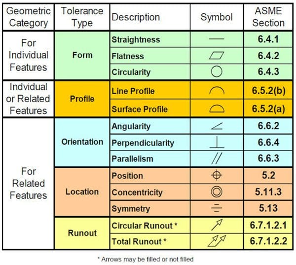
- There are 14 characteristic symbols in 5 categories; position, flatness, perpendicularity and profile are the most used.
- Datums (A, B, C) establish the reference frame the tolerances are measured from — getting them right is half the battle.
- A feature control frame packs the symbol, tolerance value, modifiers and datum references into one box.
- Modifiers MMC (Ⓜ) and LMC (Ⓛ) let a tolerance vary with feature size — useful for assembly clearance.
What is GD&T?
Plus/minus tolerances limit how much a dimension can vary, but they can’t fully describe how a feature must relate to the rest of the part — whether a face is flat, a hole is perpendicular, or a bore stays centered as it spins. GD&T adds that geometric control and ties it to datums, so the drawing captures how the part actually has to function and assemble. The two governing standards are ASME Y14.5 (North America) and ISO 1101 (international).
The 14 GD&T symbols by category
| Category | Characteristic | Needs a datum? |
|---|---|---|
| Form | Straightness | No |
| Flatness | No | |
| Circularity (roundness) | No | |
| Cylindricity | No | |
| Profile | Profile of a line | Sometimes |
| Profile of a surface | Sometimes | |
| Orientation | Angularity | Yes |
| Perpendicularity | Yes | |
| Parallelism | Yes | |
| Location | Position | Yes |
| Concentricity* | Yes | |
| Symmetry* | Yes | |
| Runout | Circular runout | Yes |
| Total runout | Yes |
*Concentricity and symmetry were removed in ASME Y14.5-2018; position or profile is used instead.
Datums: the reference frame
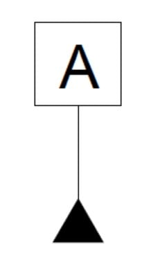
A datum is a theoretically exact reference — a plane, axis or point — established by a real feature (a face, a bore) and labeled with a letter (A, B, C). Geometric tolerances are measured relative to these datums, usually in a priority order (primary A, secondary B, tertiary C) that locks the part in space the way it functions or assembles. Choosing datums that match how the part is used, fixtured and inspected is the most important part of applying GD&T well.
The feature control frame
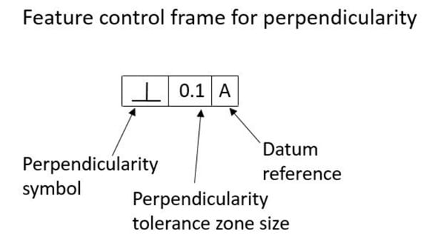
Every geometric callout is written in a feature control frame — a rectangular box read left to right: the geometric symbol, then the tolerance zone (often with a diameter symbol and a material modifier), then the datum references. For example, a position callout might read: position | ⌀0.2 Ⓜ | A | B | C — meaning the feature’s axis must lie within a 0.2 mm diameter cylindrical zone at maximum material condition, relative to datums A, B and C.
Material condition modifiers: MMC and LMC
Modifiers let a geometric tolerance change with the feature’s actual size:
- MMC (Ⓜ) — Maximum Material Condition: the most material (largest pin / smallest hole). As the feature departs from MMC, a ‘bonus tolerance’ is gained — ideal for guaranteeing assembly clearance.
- LMC (Ⓛ) — Least Material Condition: the least material (smallest pin / largest hole) — used to protect wall thickness or minimum edge distance.
- RFS — Regardless of Feature Size: the default; the tolerance stays fixed no matter the feature size.
Why GD&T matters
Applied well, GD&T communicates function unambiguously, allows the widest manufacturable tolerance (through bonus tolerance and profile), and gives inspection a clear pass/fail. Related form controls have their own guides: flatness, straightness, perpendicularity and runout.

Frequently asked questions
What does GD&T stand for?
How many GD&T symbols are there?
What is a datum in GD&T?
What does MMC mean?
What is a feature control frame?
Sources & further reading: ASME Y14.5 dimensioning & tolerancing · ISO 1101 geometrical tolerancing.
Manufacturing next step
Apply this guidance to your part
Continue to the relevant service page for process scope and buyer inputs. If your design is ready, send the current files for engineering review and quotation.
Related manufacturing resources
Continue with the process or project stage most relevant to this topic: