DFM for CNC Machining: 12 Rules to Cut Cost & Lead Time

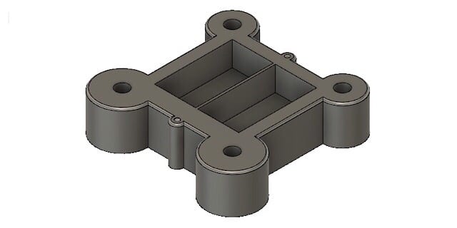
Design for Manufacturing (DFM) means designing parts around how cutting tools actually work — their size, reach and rigidity — so parts are faster, cheaper and more reliable to machine. The biggest wins come from adequate wall thickness, generous internal radii, sensible hole and pocket depths, and loosening non-critical tolerances. Here are 12 concrete rules, with target values, that cut cost and lead time without sacrificing function.
This article is part of our Design for Manufacturing hub. See also precision machining.
Key takeaways
- Design around the tool: round internal corners, reachable features, and no unnecessarily deep or thin geometry.
- Loosening non-critical tolerances is the single biggest avoidable cost saver.
- Keep walls ≥ 0.8 mm (metal) / 1.5 mm (plastic), hole depth ≤ 4× diameter, and pocket depth ≤ 4× tool diameter.
- Use standard drill and thread sizes to avoid custom tooling.
- Sendot gives a free DFM review with every quote.
What is DFM for CNC machining?
Machining removes material with rotating tools, so features that are hard to reach — or that need special tooling and extra setups — cost more. DFM is the practice of shaping the design so standard tools can make it efficiently. It is the highest-leverage point to reduce cost, because decisions locked in at design time drive most of the manufacturing expense.
12 DFM rules for CNC machining
| # | Rule | Recommended |
|---|---|---|
| 1 | Wall thickness | ≥ 0.8 mm metal, ≥ 1.5 mm plastic |
| 2 | Internal corner radii | ≥ 1/3 of pocket depth; avoid tiny radii |
| 3 | Hole depth | ≤ 4× diameter; use standard drill sizes |
| 4 | Pocket / cavity depth | ≤ 4× tool diameter |
| 5 | Tall thin features | height-to-thickness < 4:1; add ribs/fillets |
| 6 | Tolerances | ISO 2768-m default; tighten only critical dims |
| 7 | Threads | standard sizes; depth ≤ 3× diameter; don’t thread to blind-hole bottom |
| 8 | Undercuts | avoid; or design for standard tool access |
| 9 | Text / engraving | engrave (recessed) rather than emboss (raised) |
| 10 | Material | pick the most machinable that meets function (often aluminum) |
| 11 | Fillets at wall/boss base | add to reduce stress and tool load |
| 12 | Datums & setups | one clear datum; minimize the number of setups |
The rules explained
Walls & thin features (rules 1, 5, 11): thin walls and tall standoffs vibrate and deflect under cutting forces, hurting accuracy and finish — keep them thick enough and add fillets where they meet the base. Corners & pockets (rules 2, 4): end mills are round, so internal corners always have a radius; deep, narrow pockets need long, slender tools that cut slowly, so keep depth within about 4× the tool diameter. Holes & threads (rules 3, 7): standard drill and thread sizes avoid custom tooling, and threading only as deep as needed saves time. Tolerances (rule 6): only tighten what function requires — see our tolerances guide. Access & setups (rules 8, 12): features reachable from standard directions and a single datum reference reduce setups and error. Material (rule 10): browse the materials hub — aluminum machines fastest and cheapest.
How DFM cuts cost and lead time
Every avoided special tool, extra setup and unnecessary tight tolerance removes machine time and inspection — and re-quote cycles. A part designed with these rules quotes faster, machines faster, and yields more consistently, which lowers both unit cost and lead time. It ties directly into overall CNC machining cost.

Frequently asked questions
What is DFM in CNC machining?
What is the minimum wall thickness for CNC machining?
Why do internal corners need a radius?
How does DFM reduce machining cost?
How deep can a hole or pocket be?
Sources & further reading: ISO 2768 general tolerances · ASME Y14.5 dimensioning & tolerancing.
Related
THE FULL DFM GUIDE
The rules above are the CNC-specific layer of a wider discipline. For the complete pillar — DFM principles, a full worked design for manufacture example, the step-by-step DFM process, how DFM and DFA differ, and what changes across CNC, sheet metal and die casting — see our Design for Manufacturing guide.
Manufacturing next step
Apply this guidance to your part
Continue to the relevant service page for process scope and buyer inputs. If your design is ready, send the current files for engineering review and quotation.
Related manufacturing resources
Continue with the process or project stage most relevant to this topic: