What Is Sheet Metal Fabrication? Process & RFQ Guide

This guide is for mechanical and product engineers who need to understand the sheet metal fabrication process before preparing an RFQ. It maps one primary intent—what is sheet metal fabrication—to the sheet metal fabrication service. It does not replace the drawing, material specification or order-specific review.
What is sheet metal fabrication?
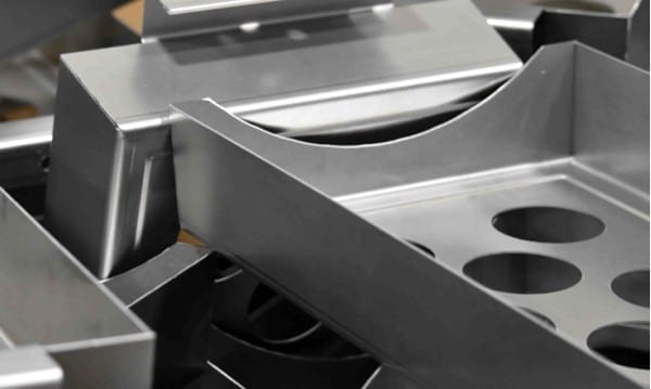
Sheet metal fabrication is a manufacturing route that converts flat metal sheet into functional parts or assemblies. A typical route may include profile cutting or punching, press-brake forming, hardware insertion, welding or mechanical joining, deburring, surface finishing and agreed inspection. Not every part needs every step, and the route should be confirmed against the released files.
The process is commonly reviewed for brackets, panels, covers, chassis and enclosures whose geometry can be developed from sheet. A solid model that looks like a box is not automatically fabrication-ready: bend feasibility, flange access, feature position, joint strategy, finish and assembly sequence still need review.
Fabrication sequence
Review → cut → form → join → finish → inspect, adjusted for the actual part and assembly.
Buyer control package
Revision → material → critical features → finish → evidence → acceptance and approval authority.
How the sheet metal fabrication process works
| Stage | What happens | Buyer input that controls the review |
|---|---|---|
| 1. File and contract review | The supplier checks the model, drawing, revision and included operations. | Part number, units, controlling file, quantity, intended use and acceptance basis. |
| 2. Material and blank planning | Material form, grade, thickness and blank arrangement are reviewed. | Material specification, thickness, grain or surface direction when relevant, and substitution policy. |
| 3. Cutting or punching | The flat profile, holes, slots and reliefs are produced using a suitable reviewed method. | Critical cut features, edge condition, cosmetic faces and any referenced cut-quality requirement. |
| 4. Forming | Bends, flanges, hems or other formed features create the three-dimensional part. | Inside radii where controlled, bend angles, datums, mating geometry and features near bends. |
| 5. Joining and hardware | Fasteners, inserts, rivets or welds create the part or assembly where required. | Hardware specification, weld symbols, joint locations, removable/permanent intent and assembly responsibility. |
| 6. Finish | Deburring and the agreed surface treatment are applied in the planned sequence. | Finish standard, color/texture reference, masking zones and protected interfaces. |
| 7. Inspection and release | Agreed characteristics and evidence are reviewed before shipment. | Critical characteristics, measurement basis, requested records and buyer acceptance authority. |
ISO 9013 classifies geometrical product specifications and quality tolerances for specified thermal cuts, but its official abstract says those requirements apply when the drawing or pertinent document references the standard. See the ISO 9013 official record. Do not assume a standard or quality class is included when it is absent from the order.
Cutting, forming and joining are one system
Cutting creates the developed blank
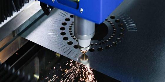
Laser cutting, punching, shearing, waterjet or another suitable route may produce a flat blank. Selection depends on the material, thickness, profile, edge requirement, quantity and downstream operations. The supplier should confirm the supported method for the actual files rather than treating one process as universally superior.
Forming turns the blank into three-dimensional geometry
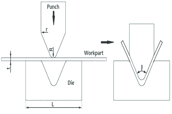
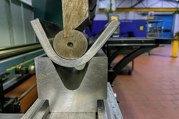
Press-brake bending and related forming operations introduce bend radius, bend allowance, tool access and springback considerations. Holes, slots and flanges near bend zones may distort or restrict tooling. A manufacturability review can flag risks, but any change to released geometry requires buyer approval.
Joining and hardware define assembly behavior
Welding, riveting, threaded fasteners and inserted hardware create different serviceability, heat-input and inspection questions. The American Welding Society A2.4 record explains that welding and examination information can be communicated by symbols. If weld size, location, extent or examination matters, place the requirement in the controlled documentation.
Design inputs to define before an RFQ
- Controlled files: current 3D model, 2D drawing, part number, revision and units; state which file controls if information conflicts.
- Material: grade/specification, thickness and condition; identify whether alternatives may be proposed or are prohibited.
- Geometry: bend radii where controlled, critical angles, datums, hole/slot relationships and mating components.
- Joining: weld or fastener definition, supplied/purchased hardware, assembly sequence and accessible service points.
- Finish: standard, color or texture reference, cosmetic faces, masking and protected electrical, sealing or grounding areas.
- Commercial scope: quote quantity, repeat quantity context, shipping destination and included operations.
- Evidence: inspection points, report or material-document request, sampling expectation and acceptance criteria agreed per order.
ASME describes Y14.5 as a common language for stating and interpreting dimensional and geometric requirements in drawings and digital product definition. Use the ASME Y14.5 official overview to understand the role of controlled design intent; it does not make every dimension critical or set a Sendot default tolerance.
Make sheet metal quotes comparable
- Freeze the comparison revision. Send every supplier the same current model, drawing and scope.
- List included operations. Separate cutting, forming, hardware, joining, finish, inspection, packaging and freight assumptions.
- Mark critical requirements. Identify functional interfaces and evidence instead of applying tight control everywhere.
- Review supplier questions. Record proposed bend, joint, material or finish changes as open items.
- Obtain buyer approval. Release accepted changes or deviations through the buyer’s change process.
- Compare the full task. Evaluate the same quantity, revision, operations, evidence and delivery basis—not headline price alone.
The Protolabs sheet metal design toolkit organizes common questions around bend radii, flange length, features near bends and hardware. A current RapidDirect process guide similarly covers cutting, forming, joining and finish. These are neutral research references; their service limits, pricing and schedules do not describe Sendot.
Watch a real sheet metal process overview
What to send for engineering review
Send the current files, material and thickness, quantity, bend and joint requirements, hardware, finish, critical features and requested evidence. Sendot can review the project against available fabrication routes and return project-specific feedback and quotation scope. The buyer remains responsible for final design release, substitution and deviation approval, and acceptance.
Frequently asked questions
What are the main steps in sheet metal fabrication?
What files should I send for a sheet metal quote?
Should the buyer provide a flat pattern?
Are inspection reports included by default?
Who approves DFM changes to a sheet metal part?
Have a sheet metal part ready for review? Share the controlled CAD, drawing, material, thickness, quantity, finish and evidence requirements.
Manufacturing next step
Apply this guidance to your part
Continue to the relevant service page for process scope and buyer inputs. If your design is ready, send the current files for engineering review and quotation.
Related manufacturing resources
Continue with the process or project stage most relevant to this topic: