CNC Machining Tolerances: Standard Chart & ISO 2768 Guide
A tolerance is the allowable variation on a dimension. For CNC machining, the typical standard (default) tolerance is about ±0.005 in (±0.125 mm), and most shops apply ISO 2768-m as the general tolerance unless you specify tighter values. Precision machining can hold critical features to ±0.01 mm or better. This guide gives you a usable ISO 2768 chart, the tolerances each process can realistically hold, how to call them out, and how tolerance choices drive cost.
See our precision machining service and the design for manufacturing hub for the bigger picture.
Key takeaways
- Standard CNC tolerance is ~±0.005 in (±0.125 mm); ISO 2768-m is the usual general tolerance applied when a drawing doesn’t state one.
- Tighter tolerances cost more — they need slower cutting, better fixturing, and more inspection. Only tighten what the function requires.
- Achievable precision depends on process, material, feature size and geometry — milling and turning can hold ~±0.025 mm on critical features.
- Use ISO 2768 (general), ISO 286 (fits/limits for shafts & holes), and ASME Y14.5 / ISO 1101 (GD&T) to communicate requirements.
- Get a DFM review and price with an project-specific quote from your CAD file.
What is a machining tolerance?
No part can be made to a perfectly exact dimension, so every dimension carries a tolerance — the total amount it may vary and still be acceptable. A callout of 20 mm ±0.1 mm means any value from 19.9 to 20.1 mm passes. Tolerances can be symmetric (±0.1), limit (20.1/19.9), or unilateral (+0.1/-0). The tighter the tolerance, the more control — and cost — it takes to hold.
Standard CNC machining tolerance
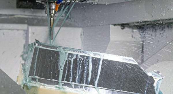
When a drawing does not specify a tolerance, most machine shops apply a standard default. In practice that is around ±0.005 in (±0.125 mm), which is comfortably achievable on typical CNC milled and turned features. Internationally this is usually formalized as ISO 2768-m (medium). Anything tighter should be called out explicitly on the drawing.
ISO 2768 general tolerance chart
ISO 2768-1 defines general tolerances for linear and angular dimensions in four classes — fine (f), medium (m), coarse (c) and very coarse (v) — so a drawing can reference one class instead of toleranceing every dimension. Permissible deviations for linear dimensions (mm):
| Nominal size (mm) | f (fine) | m (medium) | c (coarse) | v (very coarse) |
|---|---|---|---|---|
| 0.5 – 3 | ±0.05 | ±0.1 | ±0.2 | – |
| 3 – 6 | ±0.05 | ±0.1 | ±0.3 | ±0.5 |
| 6 – 30 | ±0.1 | ±0.2 | ±0.5 | ±1.0 |
| 30 – 120 | ±0.15 | ±0.3 | ±0.8 | ±1.5 |
| 120 – 400 | ±0.2 | ±0.5 | ±1.2 | ±2.5 |
| 400 – 1000 | ±0.3 | ±0.8 | ±2.0 | ±4.0 |
For fits between mating shafts and holes (e.g. H7/g6), the ISO 286 limits-and-fits system is used instead of general tolerances. Values above are the published ISO 2768-1 figures, shown here as a working reference.
Achievable tolerances by process
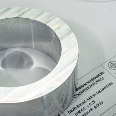
Different processes hold different precision. Typical achievable tolerances on suitable features:
| Process | Typical achievable tolerance |
|---|---|
| CNC milling | ±0.025–0.05 mm |
| CNC turning | ±0.025 mm (diameters) |
| Drilling (as-drilled) | +0.075 mm (nominal, unreamed) |
| Reaming / boring | ±0.01 mm |
| Grinding | ±0.005 mm or better |
| Wire EDM | ±0.005 mm |
What affects the tolerance you can hold?
- Material: stable metals (steel, brass) hold tighter than soft or springy materials; plastics move with temperature and humidity.
- Feature size & geometry: deep, thin or hard-to-reach features are harder to hold.
- Thermal effects: heat during cutting expands the part; large parts drift more.
- Fixturing & setups: every re-fixture adds potential error; single-setup features are most repeatable.
How to specify tolerances (and control cost)
Put a general-tolerance note on the drawing (e.g. “General tolerances per ISO 2768-m”), then tighten only the few dimensions that matter for fit or function with specific callouts or GD&T. Blanket-tight tolerances everywhere are the single biggest avoidable cost driver — each tightened dimension can require slower machining, better tooling and extra inspection. See how tolerances feed into overall CNC machining cost.

Frequently asked questions
What is the standard tolerance for CNC machining?
What is ISO 2768?
What is the tightest tolerance CNC machining can achieve?
Do tighter tolerances cost more?
What is the difference between tolerance and GD&T?
Sources & further reading: ISO 2768-1 general tolerances · ISO 286 limits & fits · ASME Y14.5 dimensioning & tolerancing.
Manufacturing next step
Apply this guidance to your part
Continue to the relevant service page for process scope and buyer inputs. If your design is ready, send the current files for engineering review and quotation.
Related manufacturing resources
Continue with the process or project stage most relevant to this topic: