Deep, Narrow Grooves and Structures with Small Clearances
Deep, narrow grooves and densely arranged thin-walled ribs are commonly found in parts such as heat sinks and valve bodies. Their original design intent is to reduce weight and increase the heat dissipation area. However, in CNC machining, these structures primarily face the following issues:
- 1. Machining deep slots requires the use of long-edge cutting tools. An excessive ratio of tool overhang to diameter can easily cause elastic deformation and vibration during cutting, leading to dimensional deviations and reduced surface quality.
- 2. The limited space in narrow slots makes it difficult for chips to be evacuated smoothly, often resulting in chip jams or even tool breakage.
- 3. Coolant struggles to reach deep, narrow areas, causing heat buildup that leads to thermal deformation of the part and affects precision.
Optimization Methods
- 1. During the design phase, appropriately increase the slot width or reduce the slot depth to ensure the ratio of tool diameter to slot depth remains within a reasonable range.
- 2. Use high-rigidity small-diameter tools or long-edge tools in combination with clamping supports.
- 3. Increase coolant flow rate or design chip evacuation grooves.
- 4. When design modifications are not feasible, employ a staged machining strategy. First performs rough machining to remove most of the material, followed by finish machining to achieve the final dimensions.
Structures with Small Radii and Incomplete Corner Clearing
Internal corner radii (R) designed too small are a common cause requiring EDM corner clearing or manual finishing. The main issues are:
- Tool diameter limitations: Theoretically, small-diameter tools are needed for R corners, but deep cavities often require long tools. However, the minimum diameter of long tools is constrained by rigidity and cannot be too small.
- Tool Path Residue: When the tool radius is larger than the R-corner specified in the drawing, unmachined material will inevitably remain at the corner, forming a “dead knot.”
- Increased Process Steps: Corner clearing that cannot be completed by CNC machining must be transferred to the EDM process, increasing clamping errors and the machining cycle time.
Optimization Methods
- 1. Within design constraints, increase the R-corner as much as possible to allow standard-diameter tools to clear the corner in a single machining.
- 2. Use helical or circular arc feed patterns at corners to avoid vibrations caused by sudden tool direction changes.
- 3. If necessary, design process notches or split structures to convert complex internal corners into external corners for machining.
Thin-Walled Structures
Thin-walled parts aim for lightweight design, but they are prone to deformation and vibration under cutting forces:
- Poor Rigidity: When the wall thickness is too thin, the part lacks sufficient rigidity, leading to elastic deformation under cutting forces.
- Lamping Difficulties: Excessive clamping force from traditional fixtures can cause part warping, while insufficient force fails to ensure stable positioning.
- Resonance Risk: Thin-walled structures have low natural frequencies, making them prone to resonance with cutting frequencies, which affects surface quality.
Optimization Methods
- 1. Add ribs or temporary supports during the design phase and remove them after machining is complete.
- 2. Use auxiliary support methods such as vacuum suction cups or low-melting-point alloy fillers.
- 3. Separate roughing and finishing operations; during finishing, adopt a “light cutting” strategy with shallow cuts, high spindle speeds, and rapid feed rates.
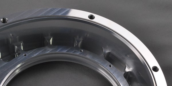
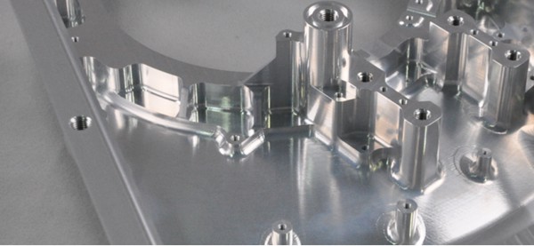
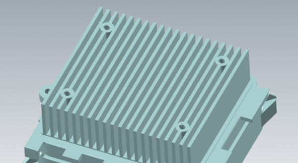
Case Study Analysis: Machining Optimization of Electric Truck Heat Sink Housing
The machining project is the heat sink housing of an electric truck. The part is made of ADC12 aluminum alloy and measures approximately 159 × 135 × 67 mm. Its primary function is to dissipate heat from the powertrain, so it was designed with a large-area, densely packed fin structure and deep grooves.
Machining Limitations with the Drawing
Upon receiving the drawings, a process review identified the following issues that severely hindered machining efficiency:
1. Unreasonable Design of Deep, Narrow Grooves in the Fin Area
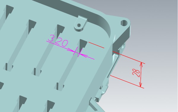
The width of the grooves between the fins is only 3.2 mm, while the groove depth reaches 28 mm. This necessitates the use of a long-fluted milling cutter with a diameter of approximately 3 mm, requiring a tool overhang of more than 29 mm. Such a slender tool has extremely poor rigidity, making it highly prone to tool breakage and vibration during machining. Furthermore, the extended machining time impacts cost calculations, and achieving the required surface roughness of Ra 1.6 is difficult.
2. Excessively Small R-Radius at the Bottom Corners of the Cavity
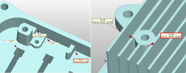
The cavity, which has a depth of 28 mm, requires an R0.5 radius at the bottom corners. To machine this deep cavity, a 3 mm diameter milling cutter must be used; however, the corner radius (R1.5) of a 3 mm cutter is significantly larger than R0.5, resulting in a large amount of material remaining unmachined at the four bottom corners. According to the original design, this would necessitate an additional EDM corner-clearing process.
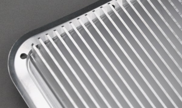
3. Excessively Thin Local Wall Thickness
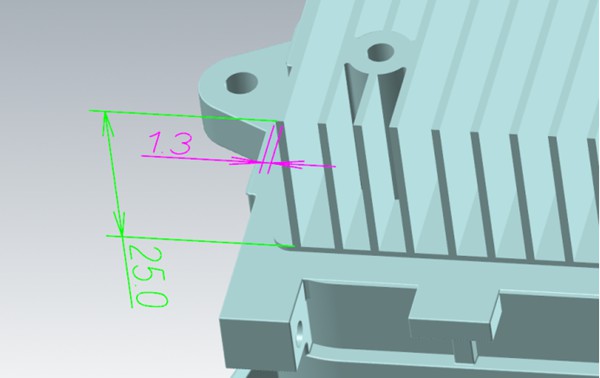
The heat sink fins have a wall thickness of only 1.2 mm and a height of 25 mm, making them prone to vibration and deformation during milling, resulting in poor dimensional stability.
Optimization Machining Plan and Implementation Results
To address the above issues, we engaged in multiple rounds of communication with the design team and implemented the following design optimizations without altering the part’s core functionality:
Optimization 1: Stepped Design for the Heat Sink Area
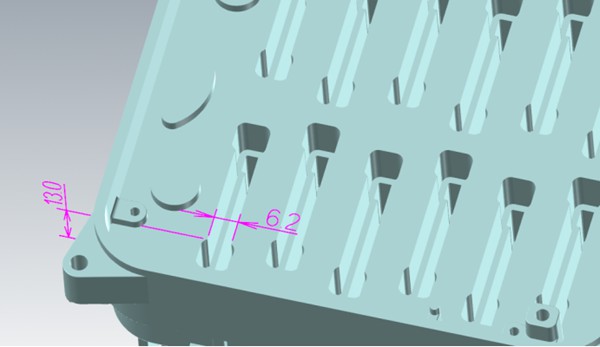
The original 28 mm deep straight groove was modified into a stepped design: the bottom 15 mm section retains a 3 mm groove width, while the upper 13 mm section is widened to 6.2 mm. This allows machining to proceed by first using a 6 mm diameter tool to machine the upper widened area, followed by a 3 mm diameter tool to machine the deep bottom groove. Although this adds one tool change, since each tool operates within a reasonable length-to-diameter ratio, cutting parameters can be increased by more than three times.
Consequently, the total machining time was reduced from the original 2.8 hours to 1.1 hours, and tooling costs were reduced by 60%.
Optimization 2: Increasing Corner Radius to Eliminate EDM Process
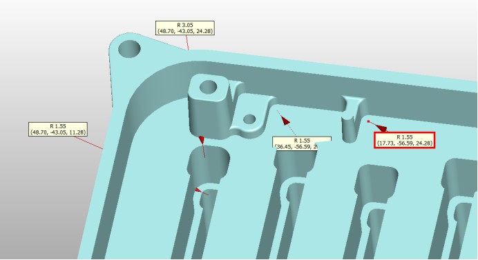
Calculations and analysis show that increasing the cavity bottom radius from R0.5 to R1.55 and changing the stepped corner to R3 have minimal impact on part assembly and strength. After modification, the entire cavity can be machined directly using 3 mm and 6 mm flat-bottom end mills, with smooth toolpath transitions and complete elimination of corner burrs. The EDM process was eliminated, allowing the part to be fully machined in a single setup, with a significant improvement in dimensional consistency.
Optimization 3: Increasing Wall Thickness in Thin-Walled Areas
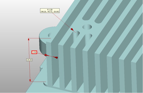
The wall thickness between the heat sinks was increased by 1.2 mm, adjusting from the original 1.3 mm to 2.5 mm. This thickening effectively suppressed tool deflection, overcutting, and deformation, stabilizing the wall thickness tolerance within ±0.05 mm.
Comparison of Machining Data Before and After Optimization
| Item | Before Optimization | After Optimization | Improvement |
| Single-part machining time | 6.5 hours | 3.2 hours | 51% reduction |
| Tool consumption | 8–10 tools/part | 4–6 tools/part | 40% reduction |
| EDM process | Retained | Eliminated | 2.5 hours saved |
| Surface roughness | Ra 1.6–3.2 | Ra 0.8–1.2 | Significant improvement |
Manufacturing Optimization Recommendations
Based on the above case analysis, the following design optimization recommendations for CNC machining can be summarized:
- Evaluate tool accessibility: When designing deep slots or holes, consider the length-to-diameter ratio limits of standard tools available on the market; generally, it is recommended that slot depth not exceed five times the tool diameter.
- Select appropriate fillet radii: Ensure internal corner fillet radii are as large as possible relative to standard tool radii to avoid EDM or manual finishing.
- Modify fin structures by increasing wall thickness or reducing the number of fins: Considering tool effectiveness and machining feasibility, convert densely spaced slots of equal depth to a stepped configuration. Thickening thin fins significantly improves tool conditions. To enhance production efficiency, reduce costs, and ensure machining stability, make appropriate minor adjustments to the part structure.