Project Introduction
For a rapid manufacturer, it’s not enough to make standard parts efficiently. The ability to machine complex components with deep cavities, multiple surfaces, and tight tolerances is equally important.

This project was carried out in cooperation with a European automation equipment manufacturer engaged in high-end transmission module development and assembly.
The component in this project, the main gearbox body, is a critical structural element at the core of the hydraulic drive system. It requires exceptional dimensional accuracy, complex geometry, and reliable sealing performance.
Part Structure Analysis
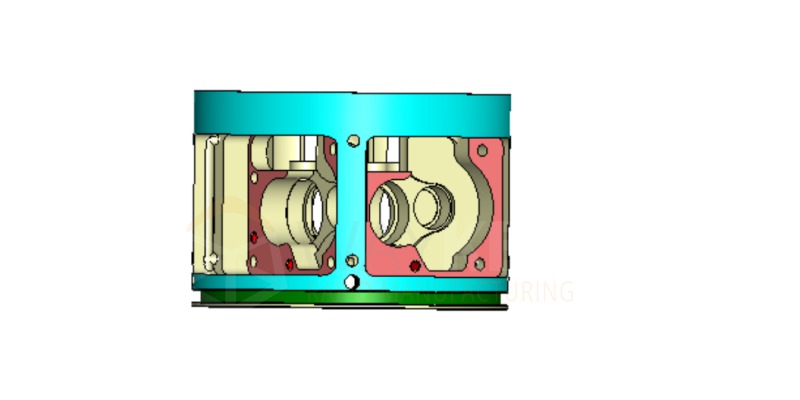
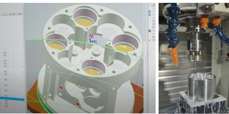
Based on the 3D model, the main gearbox features a complex multi-cavity structure with highly integrated and precise assembly requirements. The compact design includes several precision surfaces and deep holes, along with thin walls and cantilevered sections. These characteristics reduce machining stability and often require multiple setups to complete the process.
Key Machining Considerations
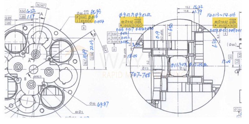
Based on the 2D drawings, the gearbox part has a complex datum structure with extremely tight precision requirements. Several critical datum surfaces and hole systems require strict control of positional accuracy, perpendicularity, and parallelism. These tolerances directly affect the assembly precision and functional performance of the part.
Multiple High-Precision Assembly Datums
As shown in the diagram:
- Red surface: Datum A
- Blue outer cylindrical surface: Datum B
- Purple surface: Datum C
- Pink surface: Datum D
- Green surface: Datum E
In the example, Datum D requires a flatness of 0.02 mm, perpendicularity of 0.03 mm, and parallelism of 0.03 mm.
Datum E is a precision hole with a G7 tolerance (+0.024 / +0.006 mm), and a positional tolerance of 0.02 mm relative to datums A, B, and D.
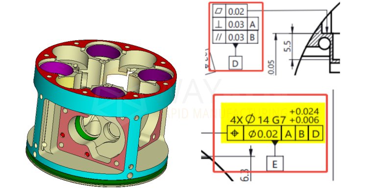
These requirements reflect a highly demanding datum system. During machining, it is essential to prioritize the geometric accuracy of each datum surface to ensure the correct foundation for all subsequent critical dimensions.
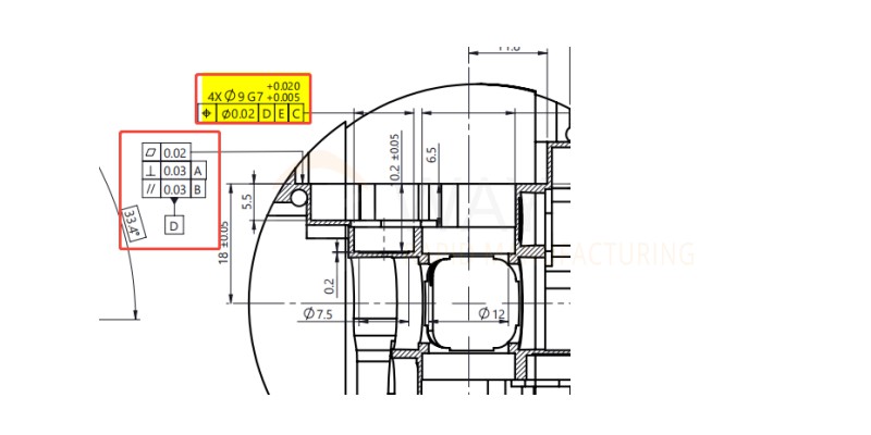
Control of Precision Holes
In addition to precision holes such as pin holes and bearing holes, the gearbox contains numerous precision holes. For example, the Ø9 precision hole shown in the diagram has a dimensional tolerance of G7 (+0.020 / +0.005 mm), referenced to datums D, E, and C, with a positional tolerance of 0.02 mm.
Ensuring Position Relationships
These datum surfaces and hole systems require not only precise control of position, perpendicularity, and parallelism but also strict adherence to the design requirements for the relationships between each datum surface and holes.
Step-by-Step Detailed Control for Custom Machining
We developed a four-step machining strategy based on three core principles: accurate datum establishment, stable fixturing, and step-by-step stress relief.
This approach ensures both the geometric accuracy of the datum surfaces and the positional accuracy of the hole systems for the gearbox body.
In addition, we implemented in-process inspection to monitor key features of the gearbox parts during each stage, ensuring structural integrity and full compliance with geometric tolerances.
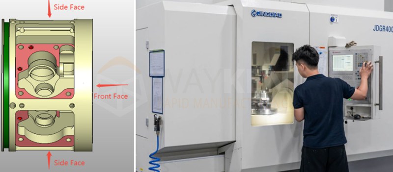
Step 1: 5-Axis Rough Machining for Stress Relief
We begin by rough machining the front and side faces, which are the largest structural surfaces of the part. This stage focuses on removing excess material and leaving a uniform machining allowance for finishing.
Using a 5-axis machining center, we complete this stage in a single setup. This maximizes machining efficiency and helps to relieve internal stress in the raw material, reducing the risk of deformation and laying a stable foundation for high-precision machining.
Step 2: 3-Axis Finishing of Back Side Datum Surfaces
After rough machining, the main gearbox part is repositioned for 3-axis finishing of the back side. This step focuses on meeting flatness and profile tolerances of the rear datum surfaces. It also ensures the accurate spatial relationship between the back datum and other key datum surfaces, laying the foundation for precise assembly alignment.
Step 3: 5-Axis Semi-Finishing for Datum and Hole Accuracy
Using custom precision fixtures, the part is re-fixtured in the same position for semi-finishing on a 5-axis machine. This stage emphasizes strict control of the relative position and perpendicularity between datum surfaces and hole systems—such as the Ø9 precision hole.
With in-process inspection integrated into this step, we continuously monitor key precision data during machining. This ensures accurate alignment of datum surfaces and holes, providing a reliable reference for the final precision hole machining.
Step 4: Final Precision Machining of Datums and Precision Holes
In the same setup, we finish all critical datum surfaces, such as A, B, C, and D. These surfaces serve as the reference for both inspection and assembly. Their flatness, surface roughness, and positional tolerances, such as parallelism and perpendicularity, are fully achieved in this stage.
Based on these completed datums, we then machine all high-precision holes of the gearbox body, including pin and bearing holes. The positional tolerances of these holes are strictly controlled according to the defined datum coordinate system. Dimensional tolerance, cylindricity, and perpendicularity/parallelism to the datums are all precisely ensured at this stage.
With unified datums and a single setup, all related tolerances are maintained.
Inspection and Quality Control: Ensuring Precision and Stability
In this project, we combined in-process measurement with CMM inspection to ensure that the gearbox body part meets the customer’s high-precision requirements at every machining stage and during final quality control.
Through the in-process measurement system, we were able to monitor and adjust the dimensions and geometric tolerances of key features in real time during machining. This allowed us to control deviations at each step promptly and effectively.
After all machining operations were completed, we performed a full precision inspection using a Coordinate Measuring Machine (CMM). This verified all critical dimensions, positions, and geometric tolerances.
The final inspection results (CMM results shown in blue above) confirmed that all key features meet the design specifications, ensuring the part’s assembly accuracy and overall stability.
Ready to Start Your Next Machining Project?
The main gearbox body was machined with complex cavities and tight tolerances using a careful 5-axis and 3-axis process.
Sendot Technology is your manufacturing expert in complex CNC machining. We ensure high-dimensional accuracy and stable performance across critical features. Our experience covers multi-axis machining of intricate cavities and tight-tolerance components. Each process is carefully planned and verified to achieve reliable, repeatable quality.