Project Background
High-precision electronic connectors rely on stable signal and power transmission to ensure overall device performance. In such applications, material selection and structural consistency are critical, as even minor geometric variations or surface defects can directly affect connection reliability and long-term stability.
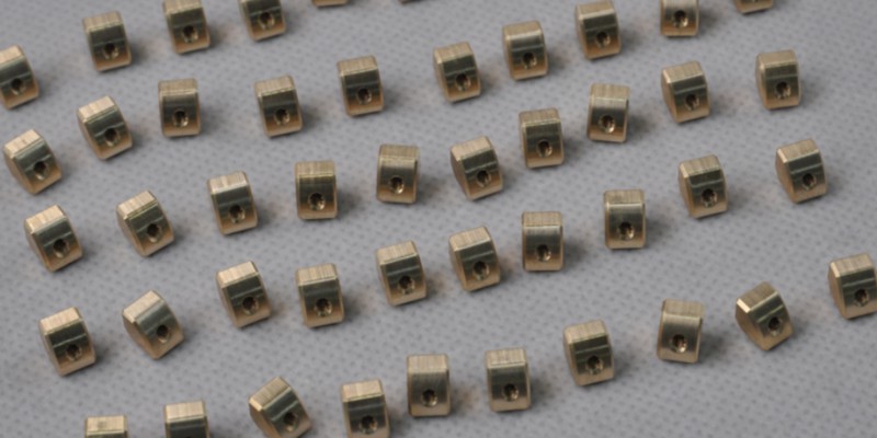
Within such connector systems, compact brass components are often used as functional elements responsible for electrical contact and signal transmission. Sendot Technology recently received a project involving 2,000 small brass components used in electronic connectors. Let’s check how the project was successfully completed.
Part Structure Analysis
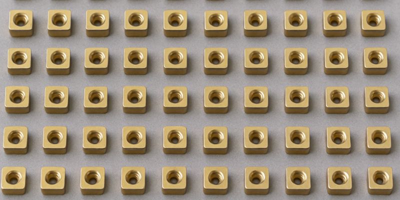
The parts feature an overall size of 6 × 7 × 5 mm, resulting in a highly compact structure with limited rigidity.
Due to the small dimensions and the material characteristics of brass, the part geometry is sensitive to deformation and burr formation, particularly around edges and small features. These structural characteristics increase the difficulty of maintaining dimensional consistency and surface quality across production.
Machining Strategy and Process Arrangement
Brass offers good machinability but is prone to burr formation, deformation, and chip accumulation, especially when machining small features. To balance precision, stability, and production efficiency, the process was designed around custom fixtures and a two-step machining strategy, ensuring consistent positioning and reliable repeatability.
Process 1: Outer Profile and Threaded Hole Machining
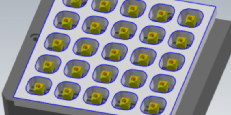
In the first operation, the part was fixed on the machining platform using a custom vacuum fixture, which provided a uniform holding force without introducing deformation. This setup allowed stable machining of the outer profile and the threaded hole.
To prevent breakthrough and maintain part integrity for the subsequent operation, a 0.1 mm allowance was intentionally left on the bottom surface. Upon completion of this step, all primary features were formed, and the outer profile was established as the primary locating reference for the next process.
Process 2: Back-Side Machining and Thread Chamfering
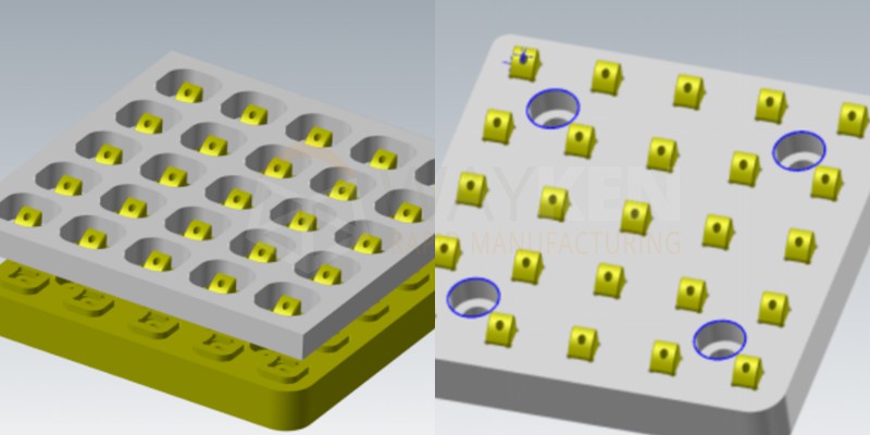
The outer profile produced in Process 1 was used as the locating reference for the second operation. A dedicated frame fixture was employed, allowing operators to load parts quickly by sliding them into position and securing the frame with screws.
This operation included back-side machining of the curved surface and chamfering of the thread entrance, bringing the part to its final geometry. The dimensional stability achieved in Process 1 ensured accurate positioning in Process 2, resulting in a stable and repeatable overall process.
Key Challenges and Practical Solutions
During batch production, several critical challenges emerged around workholding, dimensional control, chip management, and production efficiency. Check how each issue was identified and addressed in practice.
Workholding Stability: Clamping a 6 × 7 × 5 mm Brass Part
The combination of small size and soft material made conventional mechanical clamping unsuitable, as it could easily cause deformation or part movement. A vacuum fixture was therefore used in Process 1 to hold the parts via negative pressure, eliminating localized clamping stress. For the second operation, the frame fixture enabled fast and repeatable repositioning, ensuring consistency during batch production.
Dimensional Control: Why ±0.015 mm Was Required Without Drawing Tolerances?
Although no tight tolerances were specified on the drawing, the outer profile machined in Process 1 served as the locating feature for Process 2. If the profile was undersized, the part could shift within the frame fixture; if oversized, it would not fit at all.
By optimizing machining parameters and fixture design, the profile dimension was controlled within ±0.015 mm, ensuring reliable positioning and smooth downstream processing.
Chip Control: Preventing Brass Chips from Entering the Thread
During in-process inspection, fine brass chips generated during chamfering were found to fall into the threaded hole, causing thread gauge failures. Based on operator feedback, the fixture was refined by positioning the screw heads slightly above the part surface, physically blocking chips from entering the thread. This small adjustment effectively eliminated the issue and improved inspection reliability.
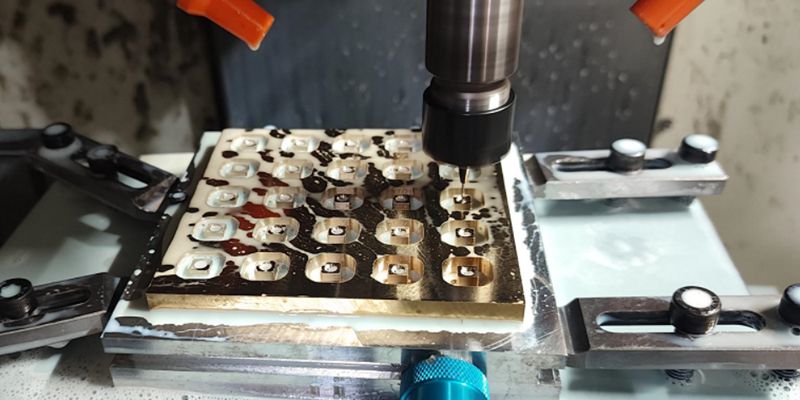
Batch Efficiency: 25 Parts per Setup Was Chosen
Machining parts individually would significantly reduce efficiency, while loading too many parts in one setup would increase the risk of scrap—since a single defect could affect the entire batch. After evaluating fixture stability, machining consistency, and yield risk, the team determined that 25 parts per setup provided the best balance between productivity and quality control.
Outcome and Support
Through well-planned process design and practical fixture solutions, Sendot Technology successfully delivered this project with stable quality and consistent results. The customer was satisfied with both accuracy and production reliability. Sendot Technology provides CNC machining services for precision metal components, with experience in process planning, custom fixturing, and stable batch production for various applications.