
5-Axis CNC Machining Robot Joint Holes: Buyer Checklist
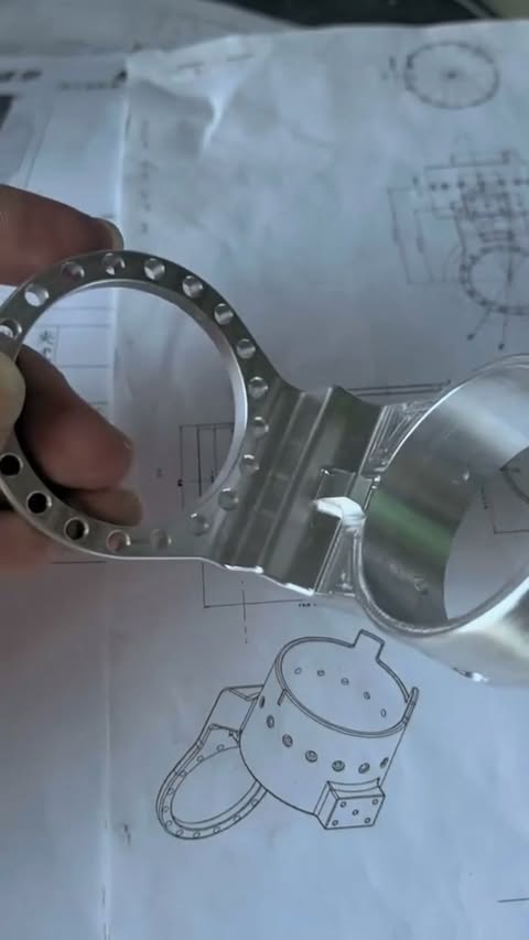
This video connects a robot-joint drawing with the finished machined component and its multi-orientation hole features. For buyers, the central question is how the supplier will preserve the relationship between bearing or shaft interfaces, mounting faces and fastener patterns. A useful RFQ identifies functional datums, fit requirements, material, finish sequence and the inspection evidence required for acceptance. Sendot's CNC and quality routes support that drawing-led review for custom joint components used in robotics or automation assemblies and related equipment. Inspection planning belongs in that review.
Direct answer
What should buyers define for robot-joint CNC machining? Define the interfaces that control motion and assembly, then connect them through a functional datum scheme. The supplier needs the model, drawing, material, finish sequence, fits, hole and thread requirements, quantity and inspection deliverables to plan machining and verify the relationships between bores, faces and mounting patterns.
What the robot-joint video shows
The Reel shows the drawing, a finished joint-shaped component and machining of features around the part. That sequence connects design intent to a physical component without assigning an unlisted model or SKU. The most useful buyer takeaway is the relationship between hole axes, faces and central interfaces. Buyers sourcing similar joint housings or structural parts can continue to the custom robot parts machining page.
Control interfaces through functional datums
A joint drawing should establish datums from the surfaces and axes used in assembly. Fits, hole position, perpendicularity or coaxial relationships can then reference that structure. Discuss the geometry through CNC machining and establish the report scope through quality assurance.
Explore similar manufacturing options
For custom robot-joint components, compare the closest machining, design-review and inspection routes:
- CNC Machining Services — Primary manufacturing service
- Design and Engineering Verification — DFM and design verification route
- Quality Assurance — Inspection planning and documentation
Technical specifications and sourcing inputs
| Attribute | Current video or sourcing definition | Source and scope |
|---|---|---|
| Component shown | Robot-joint component | Original Reel description and footage Video-specific |
| Process shown | 5-axis CNC machining | Original Reel description and footage Video-specific |
| Feature family | Multi-orientation holes and interfaces | Video footage Video-specific |
| Material and finish | Define on the controlled drawing | Customer drawing Project input |
| Datums, fits and geometric controls | Define on the controlled drawing | Customer drawing Project input |
| Inspection and sampling | Define in RFQ or purchase order | Buyer quality requirement Project input |
One-reference machining vs transferred setups for joint interfaces
| Decision factor | One-reference multi-axis plan | Transferred setup plan |
|---|---|---|
| Oriented features | Access several directions in a common setup | Reorient the part for separate directions |
| Interface relationships | Reference one established setup | Transfer datums between fixtures |
| Best fit | Interacting bores, faces and angled patterns | Separated features with clear locating surfaces |
| Inspection focus | Verify the common datum alignment | Verify both transfer and final relationships |
Robot-joint sourcing process
- Map interfaces: Identify every bearing, shaft, motor, gearbox and mounting relationship.
- Control the drawing: Apply functional datums, fits and geometric requirements.
- Review the route: Evaluate setup access, workholding, finish sequence and measurement.
- Machine: Produce features with the approved orientation and setup plan.
- Verify: Measure the agreed relationships and issue the required results.
Robot-joint RFQ and inspection checklist
- Identify bearing, shaft, motor, gearbox and mounting interfaces.
- Define the datum reference frame and relationships between hole axes.
- State fits, thread standards, inserts, protected surfaces and finish sequence.
- Provide material, quantity and revision-controlled model and drawing.
- List the characteristics and report format required for supplier acceptance.
Frequently asked questions
What should a robot-joint drawing control?
Can 5-axis machining reduce robot-joint setups?
Which files support a reliable robot-joint quote?
How are joint-hole relationships inspected?
Can Sendot quote a custom joint without a catalog SKU?
Related videos and guides
- One-Setup 5-Axis CNC Aluminum Machining
- CMM Inspection of an Aluminum Motor Housing
- CNC Machining From 3D Model to Metal Part
- GD&T Guide
- Quality Assurance Process